Y201-EN2-03.book Seite 135 Donnerstag, 30.
Y201-EN2-03.book Seite 136 Donnerstag, 30.
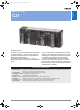
Y201-EN2-03.book Seite 137 Donnerstag, 30. März 2006 1:52 13 Programmable Controllers Modular PLC series CJ1 Sliceable Solutions The family of CJ1 CPUs range from very small CPUs for simple sequence control to powerful and fast models that offer total machine control which can handle up to 2560 I/O points. This enables yout to modularize or ’slice’ your machine into logical sections without changing PLC series.
Y201-EN2-03.book Seite 138 Donnerstag, 30. März 2006 1:52 13 Compact, fast and flexible. The CJ1-series offers the ultimate in scaleability and seamless communication. A wide variation of models to handle essentially any type of machine control. Build the perfect CJ1-series PLC for your application.
Programmable Controllers Y201-EN2-03.book Seite 139 Donnerstag, 30. März 2006 1:52 13 Program capacity The CJ1H, CJ1G, and CJ1M are compatible for memory allocations, programming instructions, and I/O Units. Compatibility simplifies reusing designs from large-scale applications to small-scale applications. Select from the range of CJ-series CPU Units including a lineup of low-end models with 160 I/O points and 5 Ksteps for use in even smaller machines.
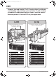
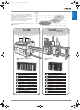
Y201-EN2-03.book Seite 140 Donnerstag, 30. März 2006 1:52 13 Downsize machines and control cabinets – fits anywhere. Super Compact: Only 90 mm High and 65 mm Deep, with I/O Units from 20 mm in width. With a height of only 90 mm, CJ1-series PLCs fit between narrow ducts along with other components. Duct 90 mm high Greatly reduces space between ducts. Power supply SSR Contactor S82K G3J J7AN Duct More power in a strongly reduced volume.
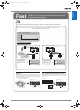
Fast Programmable Controllers Y201-EN2-03.book Seite 141 Donnerstag, 30. März 2006 1:52 13 Reduce cycle Time and Increase Productivity with Higher Machine Speed. High speed, from input through processing to output, for better application performance.
Y201-EN2-03.book Seite 142 Donnerstag, 30. März 2006 1:52 13 Seamless message communications across eight levels ( ) of component, controller, and information networks. See note The CJ Series is suitable for equipment ranging from small to large scale, making it equally convenient for building systems for essentially any machine size.
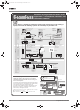
Scalable Programmable Controllers Y201-EN2-03.book Seite 143 Donnerstag, 30. März 2006 1:52 13 Distribute functionality to where you need it. Any unit fits any CPU. Eliminating the backplane enables more flexible combinations. Configurable memory allocation allows for easy machine variations. Adding or removing units does not mean you need to change your PLC program. The high-density interconnecting system forms a high-speed parallel I/O bus.
Y201-EN2-03.book Seite 144 Donnerstag, 30. März 2006 1:52 13 Easier Maintenance with Memory Cards Memory Cards Easily change programs using Memory Cards. Compact flash cards are used, enabling the Memory Cards to be shipped or mailed for speedy action even with offshore sites. Device Manufacturer Remote End User The files are received and copied to a Memory Card using Windows Explorer or other program. (CX-Programmer is not required.) Email Create Files with CX-Programmer.
Programmable Controllers Y201-EN2-03.book Seite 145 Donnerstag, 30. März 2006 1:52 13 Built-in Flash Memory (Standard Feature) Reduce Maintenance Unit Stocks Battery-free Operation Using Flash Memory The CJ1-series PLCs can be used for anything from small-scale to large-scale applications, helping to reduce the quantity of maintenance Units stocked for unexpected troubles or system expansion.
Y201-EN2-03.book Seite 146 Donnerstag, 30. März 2006 1:52 13 Greater Connectability with Component Products, with FB Compatibility (Ladder Programming/Structured Text) More Attractive to Use with Greater Development Efficiency and Maintainability FB Function Block (Unit version 3.0 or later, and CX-Programmer Ver. 5.0 or higher are required.
Programmable Controllers Y201-EN2-03.book Seite 147 Donnerstag, 30. März 2006 1:52 13 OMRON FB Library The OMRON FB library provides function blocks for setting SPs, reading PVs, and reading/writing RUN/STOP status and other Temperature Controller parameters. The programmer simply pastes function blocks from the OMRON FB Library into the ladder program. The desired functions can be utilized simply by inputting the Temperature Controller unit number and address.
Y201-EN2-03.book Seite 148 Donnerstag, 30. März 2006 1:52 13 Truly Seamless Incorporation of OMRON Components and Other Devices into Networks Serial Gateway CPU Units with Ver. 3.0 or later Serial Communications Units with Ver. 1.2 or later When the CPU Unit (Ver. 3.0 or later) or Serial Communications Board or Serial Communications Unit (Ver. 1.2 or later) receives a FINS command containing a CompoWay/F command (See note 1.
Programmable Controllers Y201-EN2-03.book Seite 149 Donnerstag, 30. März 2006 1:52 13 Serial PLC Links (Connecting Built-in RS-232C Ports on CJ1M CPU Units) Example Remote Maintenance and Monitoring of a PLC on a Trolley in an Automated Warehouse Use PLC Links for exclusive control on PCB carrier loaders and unloaders, or to exchange temperature and time information on conveyor ovens. Data links can be created between up to nine CJ1M PLCs with up to 10 words each using the built-in RS-232C ports.
Y201-EN2-03.book Seite 150 Donnerstag, 30. März 2006 1:52 13 Achieve More Flexible, More Precise Machines with Pulse I/O Control Built-in Pulse I/O CJ1M-CPU21 (5-Kstep) CJ1M-CPU22 (10-Kstep) CJ1M-CPU23 (20-Kstep) Pulse outputs: 100 kHz, 2 axes Counters: Single-phase, 100 kHz, 2 counters or Differential phases, 50 kHz, 2 counters Interrupts: 4 The above can all be used simultaneously.
Programmable Controllers Y201-EN2-03.book Seite 151 Donnerstag, 30. März 2006 1:52 13 High-speed Counter Inputs (CJ1M-CPU21/22/23) Two counter inputs, either single-phase, 100 kHz, or differential phases, 50 kHz High-speed Counter in Linear Mode High-speed Counter in Ring Mode High-speed line-driver inputs for either single-phase, 100 kHz, or differential phases, 50 kHz, can be input.
Y201-EN2-03.book Seite 152 Donnerstag, 30. März 2006 1:52 13 A Complete Lineup to mix-and-match for your application.
Programmable Controllers Y201-EN2-03.book Seite 153 Donnerstag, 30. März 2006 1:52 13 Basic I/O Units (See note.
Y201-EN2-03.book Seite 154 Donnerstag, 30. März 2006 1:52 13 CJ1H-, CJ1G-CPU@@H, CJ1M-CPU@@ CJ1 series CPU Units CJ1H-CPU6@H CJ1G-CPU4@H Slider Secures the neighboring Unit. Memory Card Indicators MCPWR (green): Lit when power is supplied to the Memory Card. BUSY (orange): Lit when Memory Card is being accessed. Memory Card Power Supply Switch Press the power supply switch to disconnect power before removing the Memory Card.
CPU Units Model I/O bits CJ1H-CPU67H 2,560 bits (Up to 3 Expansion Racks) CJ1H-CPU66H CJ1H-CPU65H CJ1G-CPU45H CJ1G-CPU45P CJ1G-CPU44H CJ1G-CPU44P CJ1G-CPU43H CJ1G-CPU43P CJ1G-CPU42H CJ1G-CPU42P CJ1M-CPU13 CJ1M-CPU13-ETN CJ1M-CPU12 CJ1M-CPU12-ETN CJ1M-CPU11 CJ1M-CPU11-ETN CJ1M-CPU23 CJ1M-CPU22 CJ1M-CPU21 Program capacity 250 kSteps 120 kSteps 60 kSteps 1,280 bits (Up to 3 Expansion Racks) 30 kSteps 960 bits (Up to 2 Expansion Racks) 20 kSteps Data memory capacity (See note.
Y201-EN2-03.book Seite 156 Donnerstag, 30.
Function Specifications Item Constant cycle time Cycle time monitoring I/O refreshing Special refreshing for CPU Bus Units I/O memory holding when changing operating modes Load OFF Input time constant setting Operating mode setting at power-up Built-in flash memory Memory Card functions Filing Debugging Online editing Program protection Error check Error log Serial communications Clock Power OFF detection time Power OFF detection delay time Memory protection Sending commands to a Host Link computer
Y201-EN2-03.book Seite 158 Donnerstag, 30. März 2006 1:52 13 Power Supply Unit Specifications Power Supply Unit Supply voltage Operating voltage and frequency ranges Power consumption Inrush current (See note 1.) CJ1W-PA205R CJ1W-PA202 100 to 240 V AC (wide-range), 50/60 Hz 85 to 264 V AC, 47 to 63 Hz 100 VA max. 50 VA max. At 100 to 120 V AC: At 100 to 120 V AC: 15 A/8 ms max. for cold start at 20 A/8 ms max.
Additional CJ1M-CPU21/22/23 Specifications Data Area Allocations for Built-in I/O I/O Code IN0 IN1 IN2 IN3 IN4 00 01 02 03 04 Address Inputs Outputs Generalpurpose inputs IN5 IN6 IN7 IN8 IN9 OUT1 OUT2 OUT3 06 07 08 09 00 01 02 CIO 2960 Bit Generalpurpose input 0 Generalpurpose input 1 Generalpurpose input 2 Generalpurpose input 3 Generalpurpose input 4 Generalpurpose input 5 OUT4 OUT5 OUT6 CIO 2961 05 General-pur- General-pur- General-pur- General-pur- --pose input
Y201-EN2-03.book Seite 160 Donnerstag, 30. März 2006 1:52 13 Built-in Output Specifications Position Control and Speed Control Item Output frequency Specifications 1 Hz to 100 kHz (1-Hz units from 1 to 100 Hz, 10-Hz units from 100 Hz to 4 kHz, and 100-Hz units from 4 to 100 kHz) Frequency acceleration and Set in 1 Hz units for acceleration/deceleration rates from 1 Hz to 2 kHz (every 4 ms). The acceleration and deceldeceleration rates eration rates can be set separately only with PLS2(887).
Y201-EN2-03.book Seite 161 Donnerstag, 30. März 2006 1:52 13 Low voltage circuit +V OUT 0 to OUT 3 COM Internal circuits Specification OUT4 to OUT5 OUT0 to OUT3 5 to 24 V DC 4.75 to 26.4 V DC 0.3 A/output; 1.8 A/Unit 6 outputs (6 outputs/common) 3.0 A/output, 10 ms max. 0.1 mA max. 0.6 V max. 0.1 ms max. 0.1 ms max. None 10.2 to 26.4 V DC 50 mA min. Internal circuits Item Output Rated voltage Allowable voltage range Max. switching capacity Number of circuits Max.
Y201-EN2-03.book Seite 162 Donnerstag, 30. März 2006 1:52 13 CJ1G-CPU@@P (Loop-control CPU Units) Specifications Providing Effective Solutions by Integrating Sequence Control and Loop Control into the Same Basic Functionality of the CJ Series Overview An engine for controlling analog quantities (e.g.
Control method Item PID control method Control combinations Model Alarms PID block internal alarms Alarm blocks CJ1G-CPU42P CJ1G-CPU43P CJ1G-CPU44P CJ1G-CPU45P PID with 2 degrees of freedom (with autotuning) Any of the following function blocks can be combined: Basic PID control, cascade control, feed-forward control, sample PI control, Smith dead time compensation control, PID control with differential gap, override control, program control, timeproportional control, etc.
Y201-EN2-03.book Seite 164 Donnerstag, 30. März 2006 1:52 13 Greater Efficiency in Team Program Development (Unit Ver. 2.0 or Later Only) Checking Address Duplication between Tasks (CX-Programmer Ver. 4.0 or Higher) Monitoring Operating Status for Each Task (CX-Programmer Ver. 4.0 or Higher) The CX-Programmer automatically executes a cross-reference report that checks whether the same addresses have been used by two or more tasks (programs) created by two or more people.
Programmable Controllers Y201-EN2-03.book Seite 165 Donnerstag, 30. März 2006 1:52 13 High-speed Processing Ample Speed for Advanced Machine Interfaces, Communications, and Data Processing High-speed Instructions and System Bus 30 Times the Overall Cycle Speed Faster Execution Times (from 20 ns) and Faster Processing of Frequently Used Instructions Faster instruction processing includes 0.02 μs for LD and 0.18 μs for MOV.
Y201-EN2-03.book Seite 166 Donnerstag, 30. März 2006 1:52 13 High-speed Exchange with Communications Units and High-speed Data Processing Response Time for both Instruction Execution and Peripheral Servicing Can Be Emphasized With CJ1G and CJ1H CPU Units, a Parallel Processing Mode can be used to perform program execution and peripheral servicing in parallel. Parallel processing doubles the speed of peripheral serving time over previous PLCs, enabling the following types of application.
Programmable Controllers Y201-EN2-03.book Seite 167 Donnerstag, 30. März 2006 1:52 13 Increased Security Various Forms of Protection Provide Better Security Conceal Intellectual Property Contained in Programs (Unit Ver. 2.0 or Later) Password Read Protection for Tasks (CX-Programmer Ver. 4.0 or Higher) Specific tasks (programs) can be set to prohibit reading unless the correct password is input. This function enables concealment of intellectual property contained in programs.
Y201-EN2-03.book Seite 168 Donnerstag, 30. März 2006 1:52 13 Instruction Features High-volume Data Processing with One Instruction Simplify Programs with Index Registers The basic data format for specifying instruction operands has been changed from BCD to binary, enabling specification of more data for each instruction. Example: BLOCK TRANSFER Instruction Index registers can be used as memory pointers to enable easily changing the addresses specified for instructions.
Y201-EN2-03.book Seite 169 Donnerstag, 30. März 2006 1:52 13 Programmable Controllers Interlock Nesting (Unit Ver. 2.0 or Later Only) (CX-Programmer Ver 4.0 or Higher) The previous interlock instructions cannot be nested. In actual applications, however, the entire interlock condition is often combined with partial interlock conditions. Multi-interlock instructions can be nested to better handle real applications.
Y201-EN2-03.book Seite 170 Donnerstag, 30. März 2006 1:52 13 PID Autotuning Simple Data Searches (Single Words) PID constants can be automatically tuned for the PID instructions. The limit cycle method is used for tuning, allowing tuning to be completely quickly. This is particularly effective when there are many PID control loops. Instructions are provided to find the maximum value, minimum value, and search values. Area of words to search specified in instruction.
High-precision Approximations Converting a level meter reading in mm to tank capacity in liters according to the shape of the tank and other difficult linear extrapolations requiring high data resolution can be performed. (Linear data can be handled as 16-bit unsigned binary or BCD data, 16-bit or 32-bit signed binary data, or floating-point decimal data.) Easily Programmed Calendar Timers (Unit Ver. 2.0 or Later) Two sets of calendar data can be compared.
Y201-EN2-03.book Seite 172 Donnerstag, 30. März 2006 1:52 13 Simulate Specific Error Statuses for Debugging Easily Handle Text Strings The FAL(006) and FALS(007) instructions can be used to simulate a desired error condition. This can be used, for example, to intentionally create error conditions in the CPU Unit while debugging to check to see if the correct error messages are displayed on a PT.
Programmable Controllers Y201-EN2-03.book Seite 173 Donnerstag, 30.
Y201-EN2-03.book Seite 174 Donnerstag, 30. März 2006 1:52 13 Dimensions Note: Units are in mm unless specified otherwise. Product Dimensions CPU Unit 2.7 CJ1M-CPU11/12/13 90 Unit/product Power Supply Unit Model number CJ1W-PA205R CJ1W-PA202 CJ1W-PD025 CJ1W-PD022 CJ1M-CPU11/12/13 CJ1M-CPU21/22/23 CJ1H-CPU@@H CJ1G-CPU@@H CJ1G-CPU@@P CJ1M-CPU1@-ETN CJ1W-TER01 CPU Unit End Cover Width 80 45 60 27 31 49 62 2.7 2.7 CJ1M-CPU21/22/23 90 31 65 73.9 2.7 83.
Y201-EN2-03.book Seite 175 Donnerstag, 30.
Y201-EN2-03.book Seite 176 Donnerstag, 30. März 2006 1:52 13 Current Consumption The amount of current/power that can be supplied to the Units mounted in a Rack is limited by the capacity of the Rack’s Power Supply Unit. The system must be designed so that the total current consumption of the Units does not exceed the maximum current for each voltage group and the total power consumption does not exceed the maximum for the Power Supply Unit.
Current Consumption Tables CJ-series Special I/O Units CPU Units and Expansion Units Name Model CPU Units (These values include current consumption for a Programming Console or CX-Programmer.) CJ1H-CPU67H/66H/65H CJ1G-CPU45P/44P/43P/42P CJ1G-CPU45H/44H/43H/42H CJ1M-CPU11/12/13 CJ1M-CPU21/22/23 CJ1M-CPU1#-ETN CJ1W-IC101 CJ1W-II101 CJ1W-TER01 Expansion Unit End Cover Current consumption at 5 V (A) 0.99 (See note.) 1.06 (See note.) 0.91 (See note.) 0.58 (See note.) 0.64 (See note.) 0.95 (See note.) 0.
Y201-EN2-03.book Seite 178 Donnerstag, 30. März 2006 1:52 13 I/O Allocations I/O Allocations In CJ-series PLCs, part of the I/O memory is allocated to each Unit. Units are divided into the following 3 groups for allocations. •Basic I/O Units •Special I/O Units •CPU Bus Units Basic I/O Units Allocations CIO Area: CIO 0000 to CIO 0079 (See note.) (Memory is allocated in word units based on mounting position in the Racks.
Y201-EN2-03.book Seite 179 Donnerstag, 30. März 2006 1:52 13 Programmable Controllers Allocations to Basic I/O Unit Groups Allocated words in the CIO Area: CIO 0000 to CIO 0079 Basic I/O Units can be mounted to the CPU Rack and Expansion Racks. Allocation Methods 1. CPU Rack Basic I/O Units on the CPU Rack are allocated words left to right (i.e., from the Unit nearest the CPU Unit) starting from CIO 0000. Units are allocated as many words as required in word units.
Y201-EN2-03.book Seite 180 Donnerstag, 30. März 2006 1:52 13 Connecting to the Peripheral Port Connecting to the RS-232C Port Peripheral port RS-232C, 9-pin (D-sub) RS-232C, 9-pin (D-sub) Connecting Cable RS-232C cable XW2Z-200S-CV (2 m) RS-232C port on CPU Unit XW2Z-500S-CV (5 m) Peripheral Port Connecting Cables Cable Length CS1W-CN226 CS1W-CN626 2.0 m 6.
Y201-EN2-03.book Seite 181 Donnerstag, 30.
Y201-EN2-03.book Seite 182 Donnerstag, 30.
DC Input/Transistor Output Units ClassificaInputs/ tion Outputs Basic I/O Unit 16 inputs/ 16 outputs Input voltage Input current (typical) 24 V DC 7 mA 32 inputs/ 32 outputs Max. output switching capacity Connections Model 12 to 24 V DC, 0.5 A/pt. 2.0 A/Unit, sinking outputs Fujitsu-compatible connector MIL connector MIL connector CJ1W-MD231 12 to 24 V DC inputs, 24 V DC outputs, 0.5 A/pt, 2 A/Unit, sourcing, load short circuit protection, alarm 12 to 24 V DC, 0.3 A/pt. 3.
Y201-EN2-03.book Seite 184 Donnerstag, 30.
Y201-EN2-03.book Seite 185 Donnerstag, 30.
Y201-EN2-03.book Seite 186 Donnerstag, 30. März 2006 1:52 13 CJ1W-OC211(SL) Internal circuits Circuit configuration Terminal arrangement Output indicator 2 A, 250 VAC 2 A, 24 VDC max.
Y201-EN2-03.book Seite 187 Donnerstag, 30.
Y201-EN2-03.book Seite 188 Donnerstag, 30.
Y201-EN2-03.book Seite 189 Donnerstag, 30.
Y201-EN2-03.book Seite 190 Donnerstag, 30. März 2006 1:52 13 CJ1W-OD263 Circuit configuration Terminal arrangement CN2 24 VDC Word m Word m+3 Word m+2 24 VDC Word m+3 Word m+1 Internal circuits Word m CN1 Word m+1 Word m+2 24 VDC 24 VDC CJ1W-OA201 Internal circuits Circuit configuration Terminal arrangement Output indicator 25 VAC max.
Y201-EN2-03.book Seite 191 Donnerstag, 30.
Y201-EN2-03.book Seite 192 Donnerstag, 30. März 2006 1:52 13 CJ1W-MD233 Circuit configuration Terminal arrangement +V OUT00 to CN1 (OUT) Word m Internal circuits OUT07 L COM Output indicator L L +V OUT08 L 12 to 24 VDC to L L OUT15 L L 0 8 20 19 9 18 17 2 10 16 15 1 3 11 14 13 12 12 11 5 13 10 9 4 6 14 8 7 15 6 5 7 COM (0V) L L L 12 to 24 VDC L L L L COM (0V) 4 3 +V +V 2 1 COM 470 Ω 3.
Y201-EN2-03.book Seite 193 Donnerstag, 30. März 2006 1:52 13 Circuit configuration Programmable Controllers CJ1W-MD263 Terminal arrangement +V OUT00 to OUT15 CN1 (OUT) Internal circuits COM0 COM0 Output indicator L Indicator switch L L +V OUT00 to Word m L L L OUT15 L L COM1 COM1 0 40 39 CN2 (IN) 8 1 9 3 11 L 38 37 2 10 36 35 L 14 13 Word m+3 5.6 kΩ IN00 to IN15 L L 1,000 pF COM0 COM0 L Word m+1 560 Ω L Indicator switch L Internal circuits Input indicator 5.
Y201-EN2-03.book Seite 194 Donnerstag, 30. März 2006 1:52 13 CJ1W-INT01 Interrupt Input Unit High-speed Response for Interrupt Task Execution: 0.37 ms OFF to ON and 0.82 ms ON to OFF • An input to the Interrupt Input Unit immediately interrupts CPU Unit processing to suspend execution of cyclic tasks (i.e., the normal programming) and execute an I/O interrupt task. System Configuration CPU Unit I/O interrupt task Specifications Input voltage 24 V DC Inputs 16 inputs Input signal pulse width No.
Y201-EN2-03.book Seite 195 Donnerstag, 30. März 2006 1:52 13 Programmable Controllers CJ1W-IDP01 High-speed Input Unit Latches input pulses as short as 50 µs. • Reads pulses that are too fast for normal I/O, such as is often requried for signal exchange with inspection devices. • Reads pulse widths (ON time) as short as 0.05 ms. • Inputs stored in the internal circuits are cleared in I/O refresh period.
Y201-EN2-03.book Seite 196 Donnerstag, 30. März 2006 1:52 13 CJ1W-TS561/-TS562 Temperature Input Units Connect up to 6 temperature sensors per Unit. These Basic I/O units allow up to 6 temperature sensors to be connected. • Input types (TS561: thermocouple J/K, TS562 : Pt100/Pt1000) can be selected per channel. • The unit presents the temperature data in the basic I/O area of the PLC occupying from 3 to 6 CIO words. • Cold junction compensation (TS561) is provided internally.
Specifications Item Inputs Input Type Measurement Range Input Assignment Output Data Conversion time Accuracy Cold Junction accuracy Sensor connection Classification: Basic I/O Unit CJ1W-TS561 (SL) CJ1W-TS562 (SL) 6 points Thermocouple types J or K (IEC 60584) 3-wire RTD types Pt100 or Pt1000 (IEC 60751) Type J: -100.0 to +850.0 °C, Pt100/Pt1000: -200.0 to +650.0 °C Type K:-200.0 to 1300.0 °C by DIP-switch, any combination of input types is possible 16-bit signed integer, resolution 0.
Y201-EN2-03.book Seite 198 Donnerstag, 30. März 2006 1:52 13 CJ1W-AD@@@(SL) Analog Input Units Convert Analog Signals to Binary Data • • • • • • • Wire burnout detection Peak-hold function Mean function Offset gain setting Range selection per intput 1/8000 resolution 2 ms conversion time for 8 channels Function Convert input signals such as 1 to 5 V or 4 to 20 mA to binary values between 0000 and 1F40 Hex and store the results in the allocated words each cycle.
Y201-EN2-03.book Seite 199 Donnerstag, 30. März 2006 1:52 13 Programmable Controllers CJ1W-DA@@@(SL) Analog Output Units Convert Binary Data to Analog Signals • • • • • Output hold Offset gain adjustment Range selection per output 1 ms conversion time per channel 1/8000 resolution Function Terminal Arrangement Binary data between 0000 to 0FA0 Hex in the allocated words can be convert to analog signals such as 1 to 5 V or 4 to 20 mA for output.
Y201-EN2-03.book Seite 200 Donnerstag, 30. März 2006 1:52 13 Specifications Item Classification: Special I/O Unit CJ1W-DA08V(SL) CJ1W-DA08C(SL) Outputs 8 points 8 points Signal Voltages 1 to 5 V Yes No range 0 to 10 V Yes No 0 to 5 V Yes No –10 to 10 V Yes No Currents 4 to 20 mA No Yes Maximum load current 2,4 mA n.a. (for voltage outputs): Maximum load resistance n.a.
Y201-EN2-03.book Seite 201 Donnerstag, 30.
Y201-EN2-03.book Seite 202 Donnerstag, 30. März 2006 1:52 13 CJ1W-PTS5@ Process Input Units Directly Input Four Temperature Sensors • Up to four temperature sensor inputs can be directly connected to a single Unit (input signal/ range shared by the four inputs) • Models with isolation between channels prevent unwanted current paths between Temperature Sensor inputs. • Measurement value alarm with hysteresis/ON delay (two inputs per channel, one of which can be set as a DO output from the Unit).
Y201-EN2-03.book Seite 203 Donnerstag, 30. März 2006 1:52 13 No. 2 Platinum-resistance Thermometer input No. 4 Platinum-resistance Thermometer input External alarm outputs L L 2b B1 2B B2 2A B3 4b B4 4B B5 4A B6 ALM2 B7 ALM4 B8 0V B9 A1 1b A2 1B A3 1A A4 3b A5 3B Programmable Controllers CJ1W-PTS52 No. 1 Platinum-resistance Thermometer input No.
Y201-EN2-03.book Seite 204 Donnerstag, 30. März 2006 1:52 13 Specifications Item Inputs Input signals Input signal ranges A/D conversion output data Conversion speed Overall accuracy Connections Unit classification Unit No. *1 Specification CJ1W-PDC15 CJ1W-PTS15 CJ1W-PTS16 2 inputs 4 to 20 mA, 0 to 20 mA, Thermocouple Pt50, Pt100 JPt100, 0 to 10 V, -10 to 10 V, B, E, J, K, L, N, R, S, T, U, Ni508.4 0 to 5 V, -5 to 5 V, 1 to 5 V, WRe5-26, PLII, -100 to 100 0 to 1.25 V, -1.25 to 1.
Y201-EN2-03.book Seite 205 Donnerstag, 30. März 2006 1:52 13 Programmable Controllers CJ1W-TC@@ Temperature Control Units One Unit Functions as Four Temperature Controllers • Supports 2-loop or 4-loop PID control or ON/OFF control. • The PID constants for PID control can be set using auto-tuning (AT). • Select either forward (cooling) operation or reverse (heating) operation. • Input directly from temperature sensors.
Y201-EN2-03.book Seite 206 Donnerstag, 30. März 2006 1:52 13 Platinum Resistance Thermometer Temperature Control Units CJ1W-TC101 (4 loops, NPN outputs) Input 2 B’ Input 2 B Input 2 A Input 4 B’ Input 4 B Input 4 A Output 2 Output 4 0 V COM (−) B1 B2 B3 B4 B5 B6 B7 B8 B9 A1 A2 A3 A4 A5 A6 A7 A8 A9 Input 1 B’ Input 1 B Input 1 A Input 3 B’ Input 3 B Input 3 A Output 1 Output 3 24 V CJ1W-TC103 (2 loops, NPN outputs, HB alarm) Input 2 B’ Input 2 B Input 2 A N.C.
Y201-EN2-03.book Seite 207 Donnerstag, 30. März 2006 1:52 13 Programmable Controllers CJ1W-NC@@ Position Control Units High-speed, High-precision Positioning with 1, 2, or 4 Axes • Simple positioning systems can be created by directly specifying operation from the CPU Unit when required. • Positioning data is saved in internal flash memory, eliminating the need to maintain a backup battery.
Y201-EN2-03.book Seite 208 Donnerstag, 30.
Specifications Motion Control Unit Model Classification Applicable PLCs Control Method Controlled devices Programming language Controlled axes Operating modes Automatic/Manual Mode CJ1W-MCH71 CJ-series CPU Bus unit CJ-series V. 2.0 or later MECHATROLINK-II (Position, Speed and Torque control ) Sigma-II series Servo Drives (ver. 38 or later) with MECHATROLINK-II Interface and various I/O Units.
Y201-EN2-03.book Seite 210 Donnerstag, 30. März 2006 1:52 13 CJ1W-NCF71 - MECHATROLINK-II Position Control Unit Multi-axes Position Controller over highspeed MECHATROLINK-II • Up to 16 axes controlled with minimum wiring. Only one cable between devices is needed. • High-speed bus MECHATROLINK-II is specially designed for Motion Control • Supports Position, speed and Torque control • Positioning can be done by direct Ladder commands.
Programmable Controllers Y201-EN2-03.book Seite 211 Donnerstag, 30. März 2006 1:52 13 Specifications Position Control Unit Model Classification Applicable PLCs Possible unit number settings Control Method Controlled devices Controlled axes CJ1W-NCF71 CJ-series CPU Bus unit CJ-series 0 to F MECHATROLINK-II (Position, Speed and Torque control ) Sigma-II series Servo Drives (ver.
Y201-EN2-03.book Seite 212 Donnerstag, 30. März 2006 1:52 13 JUSP-NS115 - Mechatrolink-II Interface Unit Item Type Applicable Servo Drive Installation Method Basic Specifications MECHATROLINK -II Communications Command Format Position Control Functions Fully Closed System Specifications Input Signals Internal Functions Power Supply Method Power Consumption Baud Rate / Transmission Cycle Details JUSP-NS115 SGDH-E models (Version 38 or later) Mounted on the SGDH Servo Drive side: CN10.
Y201-EN2-03.book Seite 213 Donnerstag, 30. März 2006 1:52 13 Programmable Controllers CJ1W-CT021 High-speed Counter Unit High-speed, flexible control with a wide array of features • • • • • • Input frequencies to 500 kHz. 32-bit counting range. Variable digital noise filter provided. 5-/12-/24-V line driver inputs Supports simple, ring, and linear counting modes.
Y201-EN2-03.book Seite 214 Donnerstag, 30. März 2006 1:52 13 CJ1W-CTL41-E 4-Channel Counter Unit • 4 independent counter channels for encoder or pulse train inputs • 4 Counter channels with 32-bit counter value • Linear or circular counter mode selectable per channel. • Max.
CJ1W-CTS21.fm Seite 215 Mittwoch, 12. April 2006 10:14 10 Programmable Controllers CJ1W-CTS21-E SSI Encoder Input Unit 2 independently configurable inputs for SSIcompatible sensors • SSI (synchronous serial interface) is a standard communication protocol mainly used for absolute encoders or distance measurement systems. • It provides more flexibility, easier connection and reduced wiring compared to parallel connection of absolute encoders.
Y201-EN2-03.book Seite 216 Donnerstag, 30.
Y201-EN2-03.book Seite 217 Donnerstag, 30. März 2006 1:52 13 Programmable Controllers Protocol Macros Easily Create Protocols for Data Exchange with External Devices Using One Instruction Function Types of Protocol Data transfer protocol for serial communications vary with the manufacture and with devices. Differences in protocols can make communications between devices by different manufactories very difficult, even when electrical standards are the same.
Y201-EN2-03.book Seite 218 Donnerstag, 30. März 2006 1:52 13 Other Protocols Host Links 1:N NT Links with High-speed Links Host Link (C-mode) commands or FINS commands placed within host link headers and terminators can be sent to a host computer to read/ write I/O memory, read/control the operating mode, and perform other operations for the PLC.
Y201-EN2-03.book Seite 219 Donnerstag, 30. März 2006 1:52 13 Programmable Controllers CS1W-SCU@1-V1 Serial Communication Unit Support Protocol Macros, Host Link Communications, and 1:N NT Links • Mount up to 16 Units (including all other CPU Bus Units) on CPU or Expansion Racks. Ideal for systems that required many serial ports. Function The SCU21 and SCU41 CPU Bus Unit can be used to increase the number of serial ports (RS-232C or RS-422A/485) two at a time.
Y201-EN2-03.book Seite 220 Donnerstag, 30. März 2006 1:52 13 CJ1W-CIF11 RS-422A Adapter Converts RS-232C to RS-422A/RS-485 • Use to convert RS-232C to RS-422A/RS-485. • Simply connect this Adapter to the built-in RS-232C port or an RS-232C connector on a Serial Communications Unit (D-sub, 9-pin) to convert to RS-422A/ RS-485). Specifications Item Dimensions Weight Rated power supply voltage Current consumption Isolation Transmission distance Specifications 18.2 × 34.0 × 38.8 mm (W × H × D) 20 g max.
Y201-EN2-03.book Seite 221 Donnerstag, 30. März 2006 1:52 13 Programmable Controllers NT-AL001 RS-232C/RS-422A Adapter Unit • Long-distance transmissions are possible through an RS-422A interface. By converting from RS-232C to RS-422A and then back to RS-232C, a transmission distance of up to 500 m can be achieved. • No power supply is required. If the 5-V terminal (150 mA max.) is connected from the RS-232C device, a separate power supply is not required to drive the Adapter Unit.
Y201-EN2-03.book Seite 222 Donnerstag, 30. März 2006 1:52 13 CJ1W-V600C1@ RFID Sensor Units Process RFID tag data directly in the control system. • Models available to connect to either one R/W Head or two R/W Heads. • High-speed data communications with the CPU Unit (160 bytes/scan). • Efficient programming with control bits and data located in different interface areas.
Programmable Controllers Y201-EN2-03.book Seite 223 Donnerstag, 30. März 2006 1:52 13 Specifications Item Data transfer speed Applicable RFID system Number of connectable R/W Heads Commands (The number of bytes that can be specified is given in brackets.) Communications processing time (See note.
Y201-EN2-03.book Seite 224 Donnerstag, 30.
Programmable Controllers Y201-EN2-03.book Seite 225 Donnerstag, 30. März 2006 1:52 13 Communications Networks Information Networks Message Communications Host computer to PLC Ethernet FinsGateway PLC to PLC or PLC to host computer. FA network middleware that supports FINS message communications. FTP Server Function Host computer to PLC. File transfers from host computer to Memory Card installed in CPU Unit. Socket Service Data transfers using TCP or UDP protocol.
Y201-EN2-03.book Seite 226 Donnerstag, 30. März 2006 1:52 13 Ethernet: Information Network Controller Link: Control Network Use an Ethernet Network to organically link production management with the production site using various communications services. Controller Link can easily connect PLCs at the factory site in a fully functional FA network.
DeviceNet: Component Network Message Communications Create a multi-vendor network for multibit communications for lowerlevel PLCs that need to handle both control signals and data. Send FINS messages between OMRON PLCs and Explicit message between OMRON PLCs and devices from other makers. Remote I/O Communications Large-capacity remote I/O can be freely allocated according to application needs.
Y201-EN2-03.book Seite 228 Donnerstag, 30. März 2006 1:52 13 CJ1W-ETN21 Ethernet Unit Enables fast data transfer within Factory Automation systems, and easily links FA systems to plant management systems • Use the standard Ethernet protocools, TCP/IP and UDP/IP, and OMRON’s standard FINS message communications. • FINS routing provides seamless communication with Controller Link, DeviceNet and other networks. • Access data files in PLC memory or on CompactFlash cards using the Unit’s FTP server function.
Programmable Controllers Y201-EN2-03.book Seite 229 Donnerstag, 30. März 2006 1:52 13 Specifications Classification CPU Bus Unit Ethernet Unit Communications services Unit numbers FINS communications service (TCP/IP, UDP/IP), FTP server 0 to F (4 Units max.) functions, socket services, mail transmission service, mail receive, automatically adjusted PLC built-in clock (remote command receive), server/host name specification.
Y201-EN2-03.book Seite 230 Donnerstag, 30. März 2006 1:52 13 CJ1W-CLK21-V1 Controller Link Units Simpler Controller Link Wiring, Startup, and Construction Provides Larger-capacity Data Links, Greater Flexibility in Area Control, and Supports Multiple Sub-networks Function The data link capacity is 20,000 words per node. Allocate both Data Link Area 1 and Area 2 in the same area. Connect up to 8 Units under a single CPU Unit. (Unit Ver. 1.
Y201-EN2-03.book Seite 231 Donnerstag, 30. März 2006 1:52 13 Previous Units supported connection of up to four Controller Link Units to a single CPU Unit. Creating a gateway to the host network to control the Controller Links as a group of sub-networks required dividing the Units between two PLCs with a maximum of four networks for a single PLC. New CS/CJ-series Controller Link Units (Wired/Optical Ring) enable connection of up to 8 Controller Link Units for each CPU Unit.
Y201-EN2-03.book Seite 232 Donnerstag, 30. März 2006 1:52 13 Specifications for Networks Using Repeaters Item Segment (See note 1.) Transmission path configuration Multi-drop Baud rate/maximum transmission dis- 2 Mbps: 500 m tance (See note 2.) 1 Mbps: 800 m 500 kbps: 1 km Maximum number of nodes Controller Link Unit + Repeater Unit Total number of nodes: 32 Maximum number of Repeater levels --(See note 3.) Total network Tree (using Repeaters to connect each segment) 2 Mbps: 1.5 km 1 Mbps: 2.
Y201-EN2-03.book Seite 233 Donnerstag, 30. März 2006 1:52 13 Programmable Controllers CJ1W-DRM21 DeviceNet Unit Multivendor, Multibit Network • Control of up to 32,000 points (2,000 words) per master. • Remote I/O communications can be allocated in any area using DM settings. • 16 DeviceNet Units can be mounted for each CPU Unit (3 max. for fixed allocations). • When using the Configurator (see note), remote I/O can be allocated in an order independent of node address.
Y201-EN2-03.book Seite 234 Donnerstag, 30. März 2006 1:52 13 Specifications DeviceNet Unit Classification CPU Bus Unit Types of communications Remote I/O communications master (fixed or user-set allocations) Remote I/O communications slave (fixed or user-set allocations) Message communications Specifications Unit numbers Up to 16 Units can be mounted 0 to F when a Configurator is used. (Configurator required to mount 16 Units.
Y201-EN2-03.book Seite 235 Donnerstag, 30. März 2006 1:52 13 Programmable Controllers CJ1W-CORT21 CAN Unit Sending and Receiving 11- or 29-bit CAN messages The CAN communication protocol is widely used in all kinds of aplications. Benefits are its high reliabilty, low price and ease of implementation. But for two CAN devices to understand eachother they must speak the same protocol (language). Many implementers of CAN comunication have made their own protocol.
Y201-EN2-03.book Seite 236 Donnerstag, 30. März 2006 1:52 13 CJ1W-PRM21 PROFIBUS-DP Master unit • PROFIBUS-DP master class one with support of DP-V1 data types. • 7 kWord I/O • Simple configuration through FDT/DTM based configurator • Special CPU unit • Handles data independent of the CPU unit, thus reducing CPU load Function The CJ1W-PRM21 is a PROFIBUS-DP Master Class1 device (DPM1).
Y201-EN2-03.book Seite 237 Donnerstag, 30. März 2006 1:52 13 Programmable Controllers CJ1W-PRT21 PROFIBUS-DP slave unit PROFIBUS-DP I/O link unit • Data link to any PLC data area • Simple configuration using max. data input 100 words and max. data output of 100 words. Max. total exchanged data 180 words.
Y201-EN2-03.book Seite 238 Donnerstag, 30. März 2006 1:52 13 CJ1W-SRM21 CompoBus/S Master Unit CompoBus/S is a high-speed I/O bus • • • • Up to 256 I/O points per Master. Up to 32 Slaves per Master. Communications cycle time: 0.5 ms (at 750 kbps). Communications distance: Up to 500 m (at 93.75 kbps). • Free wiring with any branching method for up to 200 m (in long-distance communications mode).
Communiccations Communications method Coding Connections Baud rate Communications cycle time High-speed mode Long-distance mode Media Maximum communications distance Special CompoBus/S protocol Manchester Multidrop, T-branch (requires termination) High-speed mode: 750 kbps Long-distance mode: 93.75 kbps. Set via DIP switch. (Set via DM Area, Default: 750 kbps) 0.5 ms (with 8 input and 8 output Slaves) 0.8 ms (with 16 input and 16 output Slaves) 4.0 ms (with 8 input and 8 output Slaves) 6.
Y201-EN2-03.book Seite 240 Donnerstag, 30. März 2006 1:52 13 Ordering Information International Standards The standards indicated in the „Standards“ column are those current for UL, CSA, cULus, cUL, NK, and Lloyd standards and EC Directives as of the end of September 2004.
Name Applicable Connector Terminal Blocks Servo Relay Units (See note.) Specifications MIL Flat Cable Connectors (Pressure-fitted Connectors) General-purpose type (M3 screw terminals,40-pin) Special Connecting Cables Cable length: 1 m Cable length: 1.
Y201-EN2-03.book Seite 242 Donnerstag, 30. März 2006 1:52 13 Basic I/O Units Name DC Input Units Specifications 12 to 24 V DC, 10 mA, 8 inputs 24 V DC, 7 mA, 16 inputs 24 V DC, 4.1 mA, 32 inputs 24 V DC, 4.1 mA, 32 inputs 24 V DC, 4.1 mA, 64 inputs 24 V DC, 4.
Connectors for I/O Units Applicable Units I/O Units with terminal blocks I/O Units with Fujitsu connectors Name 18-point screwless terminal block 40-pin Connector Connection Screwless Clamp/ card edge Soldered Crimped 24-pin Connector Pressure welded Soldered Crimped I/O Units with MIL connectors* 40-pin Connector 20-pin Connector Pressure welded Pressure welded Model Remarks CJ-WM01-18P-5 Replacement terminal blocks for I/O Units, pack of 5 pcs.
Y201-EN2-03.book Seite 244 Donnerstag, 30. März 2006 1:52 13 Special I/O Units Name Analog Input Units Specifications 8 inputs (1 to 5 V, 0 to 5 V, 0 to 10 V, –10 to 10 V, 4 to 20 mA) Resolution: 1/8000, Conversion speed: 0.25 ms/point 4 inputs (1 to 5 V, 0 to 5 V, 0 to 10 V, –10 to 10 V, 4 to 20 mA) Resolution: 1/8000, Conversion speed: 0.25 ms/point Analog Output Units 8 outputs (1 to 5 V, 0 to 5 V, 0 to 10 V, –10 to 10 V) Resolution: 1/4000, Conversion speed: 1 ms/point max.
Programmable Controllers Y201-EN2-03.book Seite 245 Donnerstag, 30. März 2006 1:52 13 .
Y201-EN2-03.book Seite 246 Donnerstag, 30. März 2006 1:52 13 ALL DIMENSIONS SHOWN ARE IN MILLIMETERS. To convert millimeters into inches, multiply by 0.03937. To convert grams into ounces, multiply by 0.03527. Cat. No. P04E-EN-03A 246 In the interest of product improvement, specifications are subject to change without notice.