
Datasheet

Copyright ©2017 Microscan Systems, Inc.
MicroHAWK ID-20 / ID-30 / ID-40 Configuration
Power Requirements and Pin Assignments
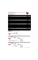
TX (+)
RX (–)
RX (+)
TX (–)
V+
V–
M12 8-Pin Socket (Ethernet)
V+
V–
MicroHAWK ID-20: 5VDC ± 5%; 350mA at 5VDC (typ.)
MicroHAWK ID-30: 5V ± 5%; 600mA at 5VDC (typ.)
MicroHAWK ID-40: 4.75V – 30V; 150mA at 24VDC (typ.)
Important: See the MicroHAWK ID-20 / ID-30 / ID-40 User Manual for information about Microscan’s Isolation Mounting Kit
(P/N 98-9000064-01) to eliminate ground loops or other external electrical noise through your MicroHAWK ID-30 or ID-40 reader.
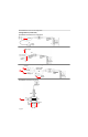
MicroHAWK ID-20 Micro-USB Type B Socket
Pin Function
1 Vbus (5V)
2 D–
3 D+
4 N/C
5 Ground
MicroHAWK ID-30 High-Density 15-Pin Dsub
USB/Serial Socket
Pin Function
1 +5VDC
2 TX232
3 RX232
4 GND
5 D+
6 N/C
7 Output 1+
8 Default+
9 Trigger+
10 D–
11 Output 3+
12 Input+ (New Master+)
13 Chassis
14 Output 2+
15 Vbus
Note: An accessory
cable is required
between the ID-30’s
15-pin corner-exit
cable and the host’s
USB port.
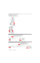
MicroHAWK ID-40 M12 Connectors
Ground
Output 3
Output 1
Output 2
New Master
Default
Power
Input Common
Output Common
RS-232 (Host) RxD
Trigger
RS-232
(Host) TxD
M12 12-Pin Plug
+10-28V
Trigger
Ground
Trigger/New Master / Input 1 Common
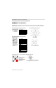
QX-1 Interface Device – for use with the MicroHAWK ID-40 (Top View)
QX-1 Trigger Connector (T) 4-pin Socket
Connector T on the QX-1
Interface Device is the
trigger connector.
Connectors 1, 2, and 3
can be used to bus power
and data as required by
the application.
P
T