
User`s manual

00042994.DOC, Version 2.0
22/33
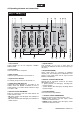
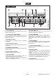
4.2 Operating elements and connections
1 Tone controls
3-band equalizer for the DJ microphone: TREBLE,
MIDDLE, BASS.
2 Level control
Level control for the DJ microphone.
3 Gain controls
A
djust the input amplification for the channels 1-4.
4 Input selector switches
For selecting the input source for the channels 1-4.
5 Output level LED meter L/R
10-digit LED meter; depending on the position of the
selector switch LED METER it indicates the level o
f
master channel 1 or of master channel 2 within the range
of -24 dB to +9 dB.
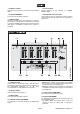
6 Selector switch LED METER
Button for switching the LED level meter between the
master channels 1 and 2.
• M2 (button pressed, red LED lights): level indication o
f
master channel 2
• M1 (button released, blue LED lights): level indication o
f
master channel 1
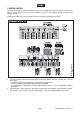
7
Inputs LINE 10
Input (optionally 3.5 mm jack or stereo RCA) fo
r
connecting an additional unit with line level output (e.g.
CD player).
8 Output REC(CORD)
Stereo output (RCA) for connecting an additional
recording unit. The recording level is independent of the
position of the master fader and the output controls
MASTER 2 and BOOTH.
9 Selector switch DJ MIC TO REC
Switches the DJ microphone channel at the outputs
REC(CORD) on and off.
• + (button pressed, red LED lights): recordings with
microphone signal
• - (button released, blue LED lights): recordings without
microphone signal
10 Control BOOTH
Level control for the output BOOTH.
11 Selector switch STERO/MONO
Stereo/mono switch for the master channels 1 and 2.
• MONO (button pressed, red LED lights): maste
r
channels are switched to mono
• STEREO (button released, blue LED lights): maste
r
channels are switched to stereo