
iConverter User Manual

AA AAAAAAAAAA AAAAAAA
BBBBBBBBBBBBBBBBBBB
1
2
3
4
5
678910
11 12
13
14
15 16
17
18 19
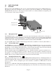
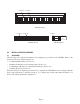
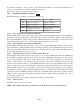
“A” Data bus “B” Data bus
19-Module Chassis
AB
12
3
4
5
AB ABAB AB
12
4
5
3
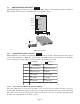
“A” Data bus “B” Data bus
AB
Managed Power Chassis
by Omnitron Systems Technology, Inc.
iConverter
™
“A” Data bus
AB
5-Module Chassis 2-Module Chassis
3.0 INSTALLATION PROCEDURE
3.1 OVERVIEW
The following steps outline the installation and configuration procedures for the GX/TM2. Refer to the
specified sections for detailed instructions.
• Configuring DIP-switches (Section 3.2)
• Installing the Module and Connecting Cables (Section 3.3)
• Configuring the Module via Command Line Interface (Section 3.4)
• Verifying Operation (Section 3.5)
When the setup and configuration procedures are completed, the GX/TM2 has been configured with the
basic setup requirement for standard operation. To configure the module with additional features, see
Section 4.0, “Detailed Module Configuration”.
Page 5