iConverter® GX/TM2 Media Converter and Network Interface Device STANDALONE AND PLUG-IN MODULE USER MANUAL Release 3.
Table of Contents 1.0 1.1 1.1.1 2.0 2.1 2.1.1 2.1.2 2.1.3 3.0 3.1 3.2 3.2.1 3.2.2 3.3 3.4 3.4.1 3.4.2 3.4.3 3.4.4 3.5 4.0 4.1 4.1.1 4.1.2 4.2 4.2.1 4.2.2 4.2.3 4.2.4 4.2.5 4.2.6 4.2.7 4.2.8 4.2.9 4.2.10 4.2.11 5.0 6.0 6.1 6.1.1 6.1.2 6.1.3 7.0 Overview .................................................................................................................... 3 General Description ....................................................................................................
1.0 OVERVIEW This document describes the installation and configuration of the iConverter GX/TM2 standalone Network Interface Device and plug-in modules. The difference between the module types are indicated using the following legend throughout this User Manual: 1.
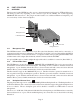
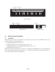
2.0 PORT STRUCTURE 2.1 OVERVIEW The front panel of the GX/TM2 provides access to the management (serial console), UTP and fiber ports. The fiber port will vary depending on the connector type; ST, SC, MT-RJ, LC or SFP supporting 1000BASE-FX transceivers. The plug-in module features two additional Ethernet backplane ports for connectivity via the chassis backplane. Fiber Port Management Port UTP Etherent Port Fiber Port UTP Etherent Port Management Port 2.1.
“A” Data bus “B” Data bus A A A A A A A A A A A A A A A A A A A B B B B B B B B B B B B B B B B B B B 1 2 3 4 5 6 7 8 9 10 11 12 13 14 15 16 17 18 19 19-Module Chassis “A” Data bus “B” Data bus B A A B 1 1 2 2 “A” Data bus B A A B 3 3 B 5 4 INSTALLATION PROCEDURE 3.1 OVERVIEW A A B B Managed Power Chassis iConverter™ by Omnitron Systems Technology, Inc. 5 4 5-Module Chassis 3.
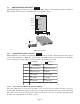
3.2 CONFIGURING DIP-SWITCHES PI SA The GX/TM2 plug-in module has two board-mounted DIP-switches. The standalone unit has one bank of DIP-switches. The locations of the DIP-switches are illustrated below. Switch 1 Bank 2 Switch 4 Switch 1 Bank 1 Switch 8 Left Right Up Bank 1 SW1 SW8 Down DIP-switch Locations 3.2.1 Board-Mounted Bank 1 Settings PI SA DIP-switch Bank 1 is available on both the plug-in and standalone modules.
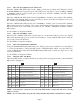
NOTE: When the fiber optic port operates in Auto-Negotiation mode, the port advertises for Pause. When the fiber optic port operates in Manual mode, Pause is disabled. NOTE: The fiber optic port of the GX/TM2 works in Full-Duplex mode in both Auto and Manual Negotiation modes. 3.2.1.2 SW2 - UTP Auto/Manual Negotiation “AN/Man” When this DIP-switch is in the “AN” position (factory default), the UTP port automatically determines the Speed, Duplex and Pause mode of the connecting UTP device.
3.2.1.3 SW3 - UTP Speed Gigabit/10-100 “1000/10-100” When the “1000/10-100” DIP-switch is in the “1000” position (factory default), the UTP always operates in 10/100/1000Mbps Auto-Negotiation mode. The UTP port auto-negotiates to a speed of 10Mbps, 100Mbps or 1000Mbps with the connected UTP device. In this mode, the UTP “AN/Man” and UTP “100/10” DIP-switches have no effect.
For detailed information on the operation of the different Link Modes, download the application note “iConverter Link Modes” available on Omnitron’s web page: http://www.omnitron-systems.com/downloads.php 3.2.2 Board-Mounted Bank 2 Settings PI DIP-switch Bank 2 is available on the plug-in module only. Switch 3.2.2.
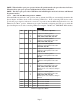
3.3 INSTALLING THE MODULE AND CONNECTING CABLES PI a. Carefully slide the module into an open slot in the chassis. Align the module with the installation guides and ensure that the module is firmly seated against the backplane. Secure the module by fastening the front panel thumbscrew (push in and turn clockwise to tighten) to the chassis front. Verify the “Pwr” LED is ON (indicating the chassis is powered). SA a.
3.4 CONFIGURING THE MODULE VIA COMMAND LINE INTERFACE PI SA To configure, attach the GX/TM2 to a DB-9 serial (RS-232) equipped computer with terminal emulation software such as HyperTerminal. The GX/TM2 Serial Console Port (DCE) is a mini DIN-6 female connector which can be changed to a DB-9 connector with the included adapter (Part #8082-0). Attach the ends of a serial cable to the serial port of the PC and the Serial Console Port of the GX/TM2. This is a standard asynchronous serial interface.
A new GX/TM2 module does not have a password, and will skip the Password Entry screen and go straight to the Management Options screen. If a password has been set, the Password Entry screen will be displayed. Type the password and press , the GX/TM2 will respond with the Management Options screen. PI SA Omnitron Systems Technology, Inc. Copyright 2001-2007 OST, Inc.
3.4.1 Setting IP and Control Preferences An IP address is required for the SNMP manager to address the GX/TM2. The factory default setting is 192.168.1.220. The IP address can be configured manually or automatically as a DHCP client. 3.4.1.1 Setting IP Parameters Manually To manually configure the IP address and control parameters, select 3 from the Management Options screen. The IP and Control Preferences screen will appear.
3.4.1.2 Setting IP Parameters as DHCP Client To configure the IP automatically as a DHCP client, select 9 from the Management Options screen. The Other Networking Features screen will appear.
NOTE: When the NMM is installed into the chassis and is set to Remote OAM, the chassis number of the GX/TM2 is automatically assigned by the NMM. PI SA IP and Control Preferences Screen iConverter, Serial Agent 1: 2: 3: Set IP Set Subnet Mask Set Gateway 192.168.1.220 255.255.255.0 192.168.1.
PI SA IP and Control Preferences Screen iConverter, Serial Agent 1: 2: 3: Set IP Set Subnet Mask Set Gateway 192.168.1.220 255.255.255.0 192.168.1.
PI SA SNMP Preferences Screen Chassis Number 1: sysContact 2: sysLocation 3: SNMP Writes iConverter, Serial Agent = 1 SNMP Engine ID 80001CAE03000687003B19 Omnitron (949) 250-6510 Irvine, CA USA Enabled SNMP 4: 5: 6: v1/v2c ------------------------------------------------------------------Read Community ***** Write Community ***** Agent Enabled SNMP 7: 8: 9: 10: 11: 12: V3 ----------------------------------------------------------------------Agent Enabled User 1 name (read only) guest User 2 name (
authNoPriv provides authentication based on the HMAC-MD5 algorithm and authPriv provides DES 56-bit encryption based on the HMAC-MD5 algorithm. To set User 1 security, select 10 at the SNMP Preferences screen, press and then follow the screen prompts. To set the User 2 security, select 13 at the SNMP Preferences screen, press and then follow the screen prompts. To set User 1 privacy password, select 11 at the SNMP Preferences screen, press and then follow the screen prompts.
3.4.3 Enabling/Disabling Soft-switch Reload The Soft-switch Reload function controls the configurations of the GX/TM2 and other iConverter modules managed by the GX/TM2 following a power up. To enable this feature, type 3 from the Management Options screen to access the IP and Control Preferences screen. PI SA IP and Control Preferences Screen iConverter, Serial Agent 1: 2: 3: Set IP Set Subnet Mask Set Gateway 192.168.1.220 255.255.255.0 192.168.1.
3.4.4 Access the GX/TM2 Remotely Remote access to the GX/TM2 is provided via SNMP, Telnet, FTP or an external serial modem connected to the Serial Console Port. 3.4.4.1 Accessing the GX/TM2 via NetOutlook (SNMP) The GX/TM2 module can be remotely accessed by SNMP-client software such as NetOutlook or thirdparty SNMP management software. See Setting SNMP Preferences Section 3.4.2, on how to configure the required parameters. NetOutlook Chassis View and Trap Log Screens 3.4.4.
PI SA IP and Control Preferences Screen iConverter, Serial Agent 1: 2: 3: Set IP Set Subnet Mask Set Gateway 192.168.1.220 255.255.255.0 192.168.1.
When the upload is complete, the GX/TM2 displays the update status and then automatically restarts with the newly loaded firmware. 3.4.4.4 Updating the GX/TM2 Firmware via FTP Using an FTP application, upload the new firmware into the FTP root directory of the GX/TM2. When the file transfer is complete, the GX/TM2 verifies the file and then automatically restarts with the newly loaded firmware.
3.5 VERIFYING OPERATION PI SA Once the module has been installed and configured, per Sections 3.2 - 3.4, verify the module is operational by viewing the status of the LED indicators. The table below provides a description for each LED indicator. The Power LED indicates the module is receiving power from the chassis or power cord. The plug-in module has an LED indicator for each available power supply in the chassis (the 19-Module Chassis has three, the 5-Module Chassis has two).
4.0 DETAILED MODULE CONFIGURATION 4.1 OVERVIEW PI SA The GX/TM2 has module parameters that require configuration depending on the application. The Module configuration screen is accessible by selecting the module slot number from the Chassis View screen. To access the Module configuration menu, select 1 at the Management Options screen, press . The Chassis Selection screen will be displayed. From the Chassis Selection screen, select the chassis number where the GX/TM2 module is installed.
PI Chassis View 19 Slot iConverter, Serial Agent Chassis Number = 1 Slot 1 2 3 4 5 6 7 8 9 10 11 12 13 14 15 Model 8000-0 8903-1 8911-1 N/A 8923N-1 N/A N/A N/A N/A N/A N/A N/A N/A N/A N/A Type NMM 10/100M 10/100M GX/TM2 | | | | | | | | | | | | | | | | Slot Model 16 N/A 17 N/A 18 N/A 19 N/A 20 N/A 21 8200-9 22 N/A Type Power Supply Module to View(1-22), Chassis Selection(0), (R)eset, (H)elp, E(x)it > 5 SA Chassis View 1 Slot iConverter, Serial Agent Chassis Number = 1 Slot 1 Model 8923N-1 Modu
PI Module - iConverter GX/TM2 Identifier Chassis Number Slot Number Model Number iConverter, Serial Agent = 1 = 7 = 8939N-0 Switch ON Condition OFF Condition H/W 1: Port 1 Manual Port 1 AN Off 2: Port 2 Manual Port 2 AN Off 3: Port 2 10/100 Port 2 1000 Off Serial Number = xxxxxxxx 4: Port 2 10 Port 2 100 Off Manufacturing Date = xxxxxxxx 5: Port 2 HDX Port 2 FDX Off Product Revision = xx 6: Link Propagate Link Segment Off Software Revision = xx 7: Remote Fault Normal Off 8: Symm Fault Det Normal Off LED
4.1.2 Module Management Mode (Configuration Setting 17 and 18) From the Module configuration screen, the management mode can be changed. Select option 18 to change the mode. The management mode options will be displayed.
4.2 PORT CONFIGURATION The Port configuration screen provides access to the port level configuration parameters, such as, Port Access, Bandwidth Control, L2CP Control, SFP Information, 802.3ah, Port VLANs, Tagged VLANs and cNode Loopback. To access the Port configuration screen, select C from the Module configuration screen and press . The Port configuration screen will appear.
4.2.1 Port Access The Port Access option allows the ports to be disabled/enabled while maintaining the port configuration and network link To configure Port Access, select option 11 for the Fiber port and option 12 for the UTP port from the Port configuration screen. 4.2.2 Bandwidth Control The GX/TM2 Bandwidth Control is accessed by selecting option 8 at the Port configuration screen. The GX/TM2 provides separate ingress and egress rate control on each port.
To change the egress rate, select option 3 for the fiber port or option 7 for the UTP port. The egress rates are displayed. Select the desired egress rate.
SA L2CP Control - iConverter GX/TM2 Identifier Chassis Number = 1 iConverter, Serial Agent Slot Number = 1 1: Fiber L2CP Ingress Control 2: UTP L2CP Ingress Control Model Number = 8939N-0 Forward Forward Enter Choice, Previous Screen(0), (H)elp, E(x)it > Select the appropriate option to configure the module for the desired operation. 4.2.4 SFP Information The GX/TM2 module installed with an SFP will provide general and specific information on the SFP.
PI SA SFP Information - iConverter GX/TM2 Identifier Chassis Number = 1 Slot Number = 2 iConverter, Serial Agent Model Number = 8939N-0 Port = 1 Address A0 Page Contents =================================================== 00: 03 04 07 00 10 02 00 00 00 00 00 01 03 00 14 C8 ................ 10: 37 37 00 00 43 4F 52 45 54 45 4B 20 20 20 20 20 77..xxxxxxx 20: 20 20 20 20 00 00 00 00 43 54 2D 30 31 35 35 53 ....xxxxxxxx 30: 53 50 2D 4D 42 35 4C 44 30 30 30 30 05 1E 00 84 xxxxxxxxxxxx....
4.2.5 802.3ah Parameters The 802.3ah parameters can be monitored and/or configured in the 802.3ah Control screen. • 802.3ah OAM State - The 802.3ah OAM State turns 802.3ah processing on or off for the selected port. When the port is configured as “Disabled” it will not respond to OAMPDUs (OAM Protocol Data Units). They will be dropped by the processor and not acted upon. When the port is configured as “Enabled”, it will respond to and be involved in the Discovery process and other supported 802.
remote ports are connected to the Fiber and UTP ports of the local device. The remote partner is managed by the local device via the 802.3ah OAM channel. • Discovery State - Indicates the Discovery state (“Complete”, “In Process” or “Incomplete”) of the remote ports. If “Complete” is displayed, Discovery has been completed. If “In Process”, Discovery has been initiated but no response from the local device has yet been received by the remote partner.
PI SA 802.3ah Control - iConverter GX/TM2 Identifier Chassis Number = 1 Slot Number = 7 1: 2: 3: 4: 5: 802.
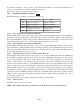
4.2.7 Port VLAN The flow of data on the module is controlled by configuring the Port VLAN settings. The block diagram below illustrates the flow of both the management traffic and the data traffic for a plug-in module (standalone modules do not have backplane access). The data traffic is controlled by a switch matrix which provides complete control of the data traffic. The management traffic is simply enabled or disabled at each port. By default traffic flows between all ports on the module.
PI Module - iConverter GX/TM2 Identifier Chassis Number Slot Number Model Number = 1 = 7 = 8939N-0 Feature Selection ---------------------------------1: 802.1Q Processing Enable Off 2: 3: 4: 5: 6: 7: 8: 9: 10: Configure Tag VLAN Control Configure VLAN Membership Save TAG VLAN Parameters Configure 802.3ah Parameters Configure 802.
4.2.8 Tagged VLAN The GX/TM2 supports the IEEE 802.1Q tag VLAN packet tagging and un-tagging (including Q-in-Q multi-tagging) and the 802.1p Quality of Service priority standards. The following parameters are configured for each port: 4.2.8.1 Port Priority (PRI) This (IEEE 802.1p based) user-specified value of 0 through 7 can be assigned as a QoS priority level (0 being lowest and 7 being highest) to packets ingressing (entering) a port.
PI Tag VLAN Control - iConverter GX/TM2 Identifier Chassis Number = 1 Slot Number = 1 Fiber 1: 2: 3: 4: 5: UTP iConverter, Serial Agent Model Number = 8939N-0 Port Priority (PRI) PVID (Port VLAN ID Tagged Packets Use Ingress Security Port Type 0 2 PVID Low Tunnel BP B 16: 17: 18: 19: 20: Port Priority (PRI) PVID (Port VLAN ID) Tagged Packets Use Ingress Security Port Type 0 2 PVID Low Tunnel 6: Port Priority (PRI) 7: PVID (Port VLAN ID) 8: Tagged Packets Use 9: Ingress Security 10: Port Type 0 2 P
4.2.9 VLAN Membership Table The VLAN Membership Table lists the permitted VLAN ID (VID) for each egress port on the module. Only packets that are assigned a VID value that matches one of the egress port’s VID memberships are allowed to egress through the port. When the Ingress Security is set to High for a specific port, the membership table is used to list the VIDs of the packets that are allowed to ingress that port. VLAN Membership is accessed by selecting option 3 from the Port configuration screen.
PI Membership Entry - iConverter GX/TM2 Identifier Chassis Number = 1 iConverter, Serial Agent Slot Number = 1 Model Number = 8923N-1 VLAN Table Membership Entry 1 -----------------------------1: 2: 3: 4: 5: 6: VLAN ID Fiber Port Membership UTP Port Membership BP A Port Membership BP B Port Membership Mngmnt Port Membership 2 No No No No No 7: Submit Entry As Defined Enter Choice, Previous Screen(0), (H)elp, E(x)it > SA Membership Entry - iConverter GX/TM2 Identifier Chassis Number = 1 Slot Number
PI Membership Entry - iConverter GX/TM2 Identifier Chassis Number = 1 iConverter, Serial Agent Slot Number = 1 Model Number = 8923N-1 VLAN Table Membership Entry 1 -----------------------------+1: +2: 3: 4: 5: 6: VLAN ID Fiber Port Membership UTP Port Membership BP A Port Membership BP B Port Membership Mngmnt Port Membership 100 Yes No No No No *7: Submit Entry As Defined Enter Choice, Previous Screen(0), (H)elp, E(x)it > SA Membership Entry - iConverter GX/TM2 Identifier Chassis Number = 1 iConv
4.2.10 cNode Loopback The GX/TM2 has implemented Iometrix cNode Level 1 agent for testing performance metrics. The agent recognizes measurement packets and loops them back to the sending cNode device. Iometrix cNode equipment is required to obtain performance metrics. cNode configuration is accessed by selecting option 10 from the Port configuration screen.
PI SA Port Statistic Module - iConverter GX/TM2 Identifier Chassis Number Slot Number Model Number iConverter, Serial Agent = 1 = 7 = 8939N-0 Port Statistics ------------------------------------------Fiber UTP Rx Bytes 0 0 Rx Packets 0 0 Rx Total Packets 0 0 Tx Bytes 0 0 Tx Packets 0 0 Enter Choice, Previous Screen(0), (H)elp, E(x)it > To refresh the Port Statistic screen, press .
5.0 GX/TM2 SPECIFICATIONS Plug-in Module Description Protocols Standalone Tabletop Standalone Wall-Mount 10/100/1000BASE-T UTP to 1000BASE-X Fiber Media Converter with integrated management 10BASE-T, 100BASE-TX,1000BASE-T, 1000BASE-X with 10,240 bytes max. frame size Cable Types UTP EIA/TIA 568A/B, Category 5 and higher Fiber Multimode: 50/125, 62.5/125, 100/140 um, Single-mode: 9/125 um Serial RS-232, 22 to 24 AWG, 12 to 50 pF/ft.
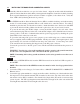
6.0 TROUBLESHOOTING GUIDE 6.1 OVERVIEW The GX/TM2 module has several LED indicators available to assist in the determination of problems. Refer to Section 3.5, Verify Operation, for LED definitions. 6.1.1 Power Issues Problem: The Power LED does not illuminate after installation is complete or no LED indicators are ON Possible Causes: A. For standalone modules, confirm that the power supply is connected to both the module and the AC or DC power source.
6.1.3 UTP Issues Problem: The UTP link LED does not illuminate after installation is complete. Possible Causes: A. Confirm that the UTP cable is connected properly to the iConverter GX/TM2 and the attached UTP device. Once a connection has been established between the iConverter and its link partner (switch or workstation), the corresponding UTP LED should illuminate. If the LED does not illuminate, check the Link Mode configuration.
7.0 WARRANTY This product is warranted to the original purchaser against defects in material and workmanship for a period of TWO YEARS from the date of shipment. A LIFETIME warranty may be obtained by the original purchaser by REGISTERING this product with Omnitron within 90 days from the date of shipment. TO REGISTER, COMPLETE AND MAIL OR FAX THE ENCLOSED REGISTRATION FORM TO THE INDICATED ADDRESS. Or you may register your product on the Internet at http://www.omnitronsystems.com.