
Media Converter and Network Interface Device User Manual
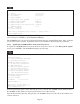

Module - iConverter 10/100M iConverter, Serial Agent
Identifier -
Chassis Number = 1 Switch ON Condition OFF Condition H/W Actual
Slot Number = 1 1: Pause Enabled Pause Disabled Off Off
Model Number = 8919-0 2: Fiber HDX Fiber FDX Off Off
3: UTP Manual UTP Auto-Neg Off Off
Serial Number = xxxxxxxx 4: UTP 10 Mbps UTP 100 Mbps Off Off
Manufacturing Date = xxxxxxxx 5: UTP HDX UTP FDX Off Off
Product Revision = x 6: Link Propagate Link Segment Off Off
Software Revision = xx 7: Remote Fault Normal Off Off
8: Symm Fault Det Normal Off Off
LED 9: BP A Enabled BP A Disabled On On
1: Power = On 10: BP B Enabled BP B Disabled On On
2: Power Supply 1 = Off 11: Not Available
3: Power Supply 2 = Off 12: Slave Only Master/Slave Off Off
4: Power Supply 3 = Off 13: Not Available
5: Fiber Link = Off 14: Not Available
6: BP Master = On 15: Not Available
7: UTP 10 Link = Off 16: Not Available
8: UTP 100 Link = Off OAM settings:
9: UTP FDX = Off 17: IP Protocol State On
18: Management Mode Secure OAM
Toggle Switch(1-16), (I)dentifier, (R)eset, (H)elp, (P)ortStat, Port(C)tl >
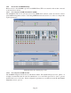
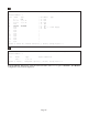
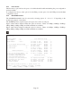
The Module configuration screen provides general information concerning the configuration and status of
the module. The screen displays the model and serial numbers, hardware and software revisions, as well as
the condition of the LEDs and DIP-switches. The DIP-switches can be re-configured (options 1 - 10, 12)
without removing the module from the chassis. Select the appropriate option to change the DIP-switch
setting. Selecting DIP-switch options 1 - 10 and 12, will cause the selection to change states under the
‘Actual’ heading.
NOTE: The Plug-In Module configuration screen is shown. The standalone Module configuration
screen will display LED 2, 3, 4, and 6 and DIP-switches 9, 10 and 12 as NOT AVAILABLE.
Page 26