iConverter® Network Management Module USER MANUAL Release 3.
Table of Contents 1.0 2.0 2.1 2.1.1 2.1.2 2.1.3 2.1.4 3.0 3.1 3.2 3.2.1 3.2.2 3.3 3.4 3.4.1 3.4.2 3.4.3 3.4.4 3.4.5 3.5 4.0 4.1 5.0 6.0 6.1 6.1.1 6.1.3 7.0 Overview .................................................................................................................... 3 Port Structure ............................................................................................................. 4 Overview ...........................................................................................
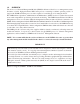
1.0 OVERVIEW The iConverter® Network Management Module (NMM) is the heart of the iConverter management system. It features a 32-bit, high performance RISC microprocessor executing a realtime operating system. It supports the SNMP and Telnet protocols and is capable of controlling up to 19 managed chassis. The NMM delivers Operations, Administration and Maintenance (OAM) services for carrier-class network access with comprehensive provisioning and network monitoring.
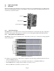
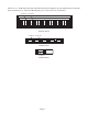
2.0 PORT STRUCTURE 2.1 OVERVIEW The Network Management Module front panel provides the access to the Management ports. Management can be accessed through the serial port or the UTP port. The module features a backplane Ethernet port for connectivity to adjacent modules. Serial Port Daisy Chain Port UTP Management Port 2.1.1 Serial Console Port The NMM features a Serial RS-232 Console Port (aka Craft Interface) for the initial setup and configuration described in this manual.
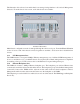
The illustration below shows how multi-chassis are managed using Omnitron’s NetOutlook Management Software. From the chassis view screen, each of the chassis are available. NetOutlook Chassis View Multi-chassis configuration can also be managed through the serial console port. From the Chassis Selection section of screen, each of the chassis connected together are available. See Section 4.0 for detailed menu screens. 2.1.
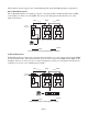
The iConverter 19-Module, 5-Module and 2-Module Chassis backplanes provide ethernet data connectivity between adjacent slots. The A and B backplane ports connect the slots as illustrated.
The backplane data bus supports Out-of-Band Management and In-Band Management configurations. Out-of-Band Management Out-of-Band Management is available by directly connecting the Network Management Station (NMS) to the UTP port on the front of the NMM. This isolates the management traffic from the rest of the traffic in the chassis.
3.0 INSTALLATION PROCEDURE 3.1 OVERVIEW The following steps outline the installation and configuration procedures for the NMM. Refer to the specified sections for detailed instructions. • Configuring Switches (Section 3.2) • Installing the Module and Connecting the UTP Cable (Section 3.3) • Configure the Module via Command Line Interface (Section 3.4) • Verify Operation (Section 3.5) When the setup and configuration procedures are completed, the NMM has been configured for operation. 3.
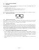
3.4 CONFIGURE THE MODULE VIA COMMAND LINE INTERFACE To configure, attach the NMM to a DB-9 serial (RS-232) equipped computer with terminal emulation software such as HyperTerminal. Using a standard serial cable, connect the serial port of the PC and the Serial Console Port of the NMM. This is a standard asynchronous DCE serial interface. The pin-outs are illustrated below.
The Management Options screen will be displayed. Management Options iConverter, Serial Agent Network Management 1: Chassis and Module Management 2: Set Module Identifier Management Module Preferences 3: IP and Control Preferences 4: SNMP Preferences 5: Abandon Preference Changes 6: Save Preference Changes 7: Restore to Factory Defaults 8: Restart Management Module 9: Other Networking Features Management Module Maintenance 10: Firmware Update 11: Set Date/Time IP Address = 192.168.1.
3.4.1 Setting IP and Control Preferences An IP address is required for the SNMP or Telnet access. The factory default setting is 192.168.1.220. The IP address can be configured manually or automatically as a DHCP client. 3.4.1.1 Setting IP Parameters Manually To manually configure the IP address and control parameters, select 3 from the Management Options screen. The IP and Control Preferences screen will appear.
3.4.1.2 Setting IP Parameters as DHCP Client To configure the IP automatically as a DHCP client, select 9 from the Management Options screen. The Other Networking Features screen will appear.
To set the Chassis Name, select 5 at the IP and Control Preferences screen, press and follow the instructions to enter the chassis name. IP and Control Preferences Screen iConverter, Serial Agent 1: 2: 3: Set IP Set Subnet Mask Set Gateway 192.168.1.220 255.255.255.0 192.168.1.
3.4.2 Setting SNMP Preferences To set the SNMP Preferences for the NMM, select 4 from the Management Options screen, press to enter the SNMP Preferences screen.
The module supports the three levels of Authentication and Encryption (Security Levels) for User 1 and User 2; noAuthNoPriv, authNoPriv and authPriv. noAuthNoPriv uses username for authentication, authNoPriv provides authentication based on the HMAC-MD5 algorithm and authPriv provides DES 56-bit encryption based on the HMAC-MD5 algorithm. To set User 1 security, select 10 at the SNMP Preferences screen, press and then follow the screen prompts.
3.4.3 Management Support 3.4.3.1 VLAN The NMM Management Processor can independently transmit and receive Management Data with an IEEE 802.1Q tag. To enable and configure this feature, type 9 from the Management Options screen to access the Other Networking Features screen.
switch settings, then the module’s hardware settings take effect. To set the Soft-switch Reload function, select 8 at the IP and Control Preferences screen, press and then follow the screen prompts to change the setting. IP and Control Preferences Screen iConverter, Serial Agent 1: 2: 3: Set IP Set Subnet Mask Set Gateway 192.168.1.220 255.255.255.0 192.168.1.
3.4.5 Access the NMM Remotely Remote access to the NMM is provided via SNMP, Telnet, FTP or an external serial modem connected to the Serial Console Port. 3.4.5.1 Accessing the NMM via NetOutlook (SNMP) The NMM can be remotely accessed by SNMP-client software such as Omnitron’s NetOutlook SNMP Management Software or third-party SNMP management software. See SNMP Preferences on how to configure the required parameters. NetOutlook Chassis View and Trap Log Screens 3.4.5.
IP and Control Preferences Screen iConverter, Serial Agent 1: 2: 3: Set IP Set Subnet Mask Set Gateway 192.168.1.220 255.255.255.0 192.168.1.
3.4.5.4 Updating the NMM Firmware via FTP Using an FTP application, upload the new firmware into the FTP root directory of the NMM. When the file transfer is complete, the NMM verifies the file and then automatically restarts with the newly loaded firmware. For detailed instructions on updating the management modules and other modules in the same chassis via FTP, download the application note “iConverter Management: Updating Modules via FTP” available on Omnitron’s web page: http://www.omnitron-systems.
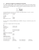
4.0 MODULE STATUS 4.1 OVERVIEW The Module status screen provide information on the NMM. The Module status screen is accessible by selecting the module slot number from the Chassis View screen. To access the Module status screen, select 1 at the Management Options screen, press . The Chassis Selection screen will be displayed. From the Chassis Selection screen, select the number of the chassis where the desired module resides.
Module - iConverter NMM Identifier - iConverter, Serial Agent Chassis Number Slot Number Model Number = = = 1 1 8000-0 Serial Number Manufacturing Date Hardware Revision Software Revision = = = = xxxxxxxx xxxxxxxx xx xx = = = = = = On Off On Off On On = Off LED 1: Power 2: Power Supply 1 3: Power Supply 2 4: Power Supply 3 5: Master(on)/Slave 6: Mgmt Activity 7: Not Available 8: Not Available 9: UTP Link Previous Screen(0), (I)dentifier, (R)eset, (H)elp, E(x)it > The Module status screen provi
5.0 NMM SPECIFICATIONS Protocols IP, UDP, SNMPv1, SNMPv2c, SNMPv3, TCP, ARP, ICMP, Telnet, FTP, 802.3ah Copper Connectors RJ-45, DB-9 Controls UTP Crossover, Frontplane/Backplane LED Displays Pwr, Pwr Supply (3), Management Link, Master/Slave, Mgt Poll Supported MIBs Dimensions RFC1155, RFC1156, RFC1157, RFC1212, RFC1213, OST MIB W: 0.85" x D: 4.5" x H: 2.8" Weight 8 oz. Power Requirements Compliance 0.32A @ 3.3VDC UL, CE, FCC, Class A, NEBS 3 Operating Temp. - Standard - Wide Temp.
6.0 TROUBLESHOOTING GUIDE 6.1 OVERVIEW The NMM module has several LED indicators available to assist in the determination of problems. Refer to Section 3.5, Verify Operation, for LED definitions. 6.1.1 Power Issues Problem: The Power LED does not illuminate after installation is complete or no LED indicators are ON Possible Causes: A. Confirm that the chassis is connected to an AC or DC power source.
7.0 WARRANTY This product is warranted to the original purchaser against defects in material and workmanship for a period of TWO YEARS from the date of shipment. A LIFETIME warranty may be obtained by the original purchaser by REGISTERING this product with Omnitron within 90 days from the date of shipment. TO REGISTER, COMPLETE AND MAIL OR FAX THE ENCLOSED REGISTRATION FORM TO THE INDICATED ADDRESS. Or you may register your product on the Internet at http://www.omnitronsystems.com.