iConverter® 5-Module Power Chassis User Manual 38 Tesla, Irvine, CA 92618 Phone: (949) 250-6510; Fax: (949) 250-6514
Warning The operating description in this Instruction Manual is for use by qualified personnel only. To avoid electrical shock, do not perform any servicing of this unit other than that contained in the operating instructions, unless you are qualified and certified to do so by Omnitron Systems Technology, Inc. Caution All user-required operations can be performed without opening the unit. Never attempt to open or remove the cover or tamper with the unit.
iConverter 5-Module Power Chassis User Manual 1. 0 GENERAL DESCRIPTION The iConverter 1U (1.75 inch) 5-Module Power Chassis is powered by up to two (2) hot-swappable and redundant universal AC or DC power supplies and can accommodate up to 5 iConverter modules. It is ideal for enterprise Local Area Network (LAN) or Metropolitan Area Network (MAN) applications where managed media converters with high density and small rack-footprint are important.
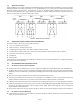
1.3 Application Example Figure 3 illustrates the connectivity of Backplane A and Backplane B when multiple modules are installed in the chassis. Modules supporting backplane connectivity (such as the iConverter 10/100M2 and iConverter 4TxVT) can be connected via the appropriate backplane creating a multi-port device. The figure show a iConverter 10/100M2 module is installed in slot 1 and a iConverter 4TxVT module is installed in slot 2. Both modules have Backplane A enabled.
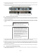
If rack mounting, mount and attach the chassis (after the mounting brackets are installed) to the rack using the appropriate rack mounting screws (not provided). Attach the AC power cords (provided for each Power Supply) to the back of each Power Supply and plug into the AC outlets. The fans should immediately begin to run and any installed modules will illuminate the power LEDs. Figure 4: iConverter 5-Module Chassis with Installed AC Power Supplies 3.
If rack mounting, mount and attach the chassis (after the mounting brackets are installed) to the rack using the appropriate rack mounting screws (not provided). Locate the DC circuit breaker and switch the circuit breaker to the OFF position. Prepare a power cable using a three conductor insulated wire (not supplied) with a 14 AWG gauge. Cut the power cable to the length required. Strip approximately 3/8 of an inch of insulation from the power cable wires.
4.2 Hot Attachment of AC Power Supply Unpack the power supply carefully. Inspect for any damage. If any damage is observed, do not use the power supply and call 949-250-6510 to report the damage immediately and request a replacement unit. Align the guide rails on the chassis with the rails on the bottom of the power supply; Slide the power supply in, ensuring that the power supply is seated firmly against the backplane and tighten the thumb screws securely with a screwdriver.
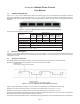
5.0 SPECIFICATIONS Chassis Type 5-Module AC 5-Module AC High Airflow 5-Module 24VDC 5-Module 48VDC 5-Module 48VDC High Airflow Model Number 8220-x 8221-2 8226-x 8225-x 8227-2 1 or 2 2 Module Capacity Power Supply Capacity Power Requirements (typical) 5 1 or 2 2 1 or 2 33 watts 66 watts 33 watts 33 watts 66 watts 100 to 240VAC 100 to 240VAC +/- 18 to 36VDC +/- 36 to 60VDC +/- 36 to 60VDC 50/60Hz 50/60Hz 1.4A @ 24VDC 0.7A @ 48VDC 2.0A @ 48VDC 0.5A @ 120VAC 1.5A @ 120VAC 10A @ 3.