
Media Converter and Network Interface Device User Manual

3.2 CONFIGURING DIP-SWITCHES
PI SA
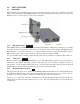
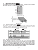
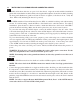
The 2GXM plug-in module has two board-mounted DIP-switches. The standalone unit has one bank of
DIP-switches. The location of the DIP-switches are illustrate below.
DIP-switch Locations
3.2.1 Board-Mounted Bank 1 Settings
PI SA
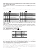
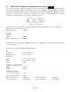
DIP-switch Bank 1 is available on both the plug-in and standalone modules. The table indicates the position
of the switch; Left/Down or Right/Up. As indicated in the DIP-switch location diagram, Left and Right
refers to the plug-in module and Down and Up refers to the standalone module.
PI
(Left/Right)
SA
(Up/Down)
Switch
Left/Down
(Factory Default)
Right/Up
SW1
AN:
Fiber Port 1 Auto-Negotiation
Man:
Fiber Port 1 Manual
SW2
AN:
Fiber Port 2 Auto-Negotiation
Man:
Fiber Port 2 Manual
SW3
Reserved Reserved
SW4 Reserved Reserved
SW5
Reserved Reserved
SW6 - SW8 See Link Mode DIP-Switch Table in Section 3.2.1.3
3.2.1.1 SW1, SW2 - Auto/Manual Negotiation “AN/MAN”
When the DIP-switch is in the Left/Down Auto-Negotiate “AN” position (factory default), the Port
automatically determines the duplex and pause modes of the connecting fiber optic devices. If the connecting
fiber optic devices cannot provide the proper signal to indicate their own mode of operation, the DIP-
switch should be set to the Right/Up Manual “MAN” position. SW1 controls Port 1; SW2 controls Port 2.
NOTE: When the fiber optic ports operate in Auto-Negotiation mode, the ports advertise for Pause.
When the fiber optic ports operate in Manual mode, Pause is disabled.
Page 6