
Instruction Manual

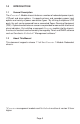
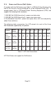

1.3 Chassis Model Numbers
Primary Power Backup Power
AC/DC
Power
SupplyModel
Contact
Closure
Two UTP
RJ-45
Ports
Low Voltage
DC-Barrel
(9-24V)
Low Voltage
DC-Terminal
(9-24V)
High Voltage
DC-Terminal
(24-60V)
RJ-45
POE
Low Voltage
DC-Barrel
(9-24V)
Low Voltage
DC-Terminal
(9-24V)
8245-111 x x Two US
8245-112 x x Two Univ.
8246-111 x x x Two US
8246-112 x x x Two Univ.
8246-511 x x x One US.
8246-512 x x x One Univ.
8247-111 x x x Two US
8247-112 x x x Two Univ.
8247-121 x x xOne US
8247-122 x x xOne Univ.
8247-220 x x x -
8247-311 x x x One US.
8247-312 x x x One Univ.
8247-320 x x x -
8248-111 x x x x Two US
8248-112 x x x x Two Univ.
8248-121 x x x xOne US.
8248-122 x x x xOne Univ.
8248-220 x x x x -
8248-311 x x x x Two US.
8248-312 x x x x Two Univ.
8248-320 x x x x -
8248-511 x x x x One US.
8248-512 x x x x One Univ.
8248-520 x x x x -
Table 1: Chassis Model Numbers
2.0 INSTALLATION
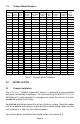
2.1 Chassis Installation
The iConverter 1-Module Redundant chassis is designed to accommodate
wall-mount or tabletop installations. For wall-mounting, the 8249-0 iConverter
Wall-Mount kit (sold separately) is designed to attach the chassis to a wall,
backboard or other flat surface.
For tabletop installations, place the unit on a flat level surface. Attach the rubber
feet to the bottom of the chassis to prevent the unit from sliding. Make sure the
unit is placed in a safe, dry and secure location.
For external power installation and configuration, see section 3.0.
Page 4