
User guide
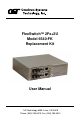
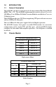
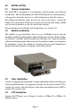
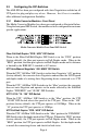
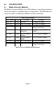
Table Of Contents
- Table of Contents
- 1.0 Introduction
- 1.1 General Description
- 1.2 Chassis Models
- 2.0 Installation
- 2.1 Chassis Installation
- 2.2 Module Installation
- 2.3 Fiber Installation
- 2.4 UTP Installation
- 3.0 Configuration
- 3.1 AC Site Preparation
- 3.2 AC Powered Chassis Mounting
- 3.3 Configuring the DIP-Switches
- 3.3.1 Media Converter Modules - Front Panel
- 3.3.2 Media Converter Modules - On-Board
- 4.0 LED Indicators
- 4.1 Media Converter Modules
- 5.0 Specifications
- 6.0 Link Modes
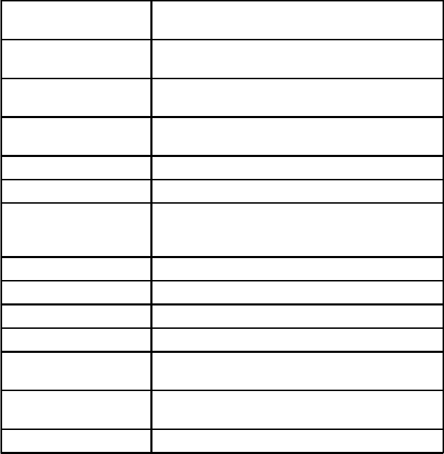
5.0 SPECIFICATIONS
Description Fast Ethernet Switch
with two 10/100 UTP Ports and two 100 Fiber Port
Protocols 10Base-T, 100Base-Tx, 100Base-Fx with 1522
bytes max. frame size
UTP Cable Type EIA/TIA 568A/B
Category 5 and higher
Fiber Cable Type Multimode: 50/125, 62.5/125, 100/140um
Singlemode: 9/125um
UTP Connector Type RJ45
Fiber Connector Type Dual Fiber: ST, SC
DIP-Switches Fiber: FDX/HDX
UTP: AN/MAN, 10/100, FDX/HDX
Link Modes: LS, LP, RFD
Power Requirements 100 - 240 VAC @ 0.5A/0.4A, 50/60Hz
Dimensions W:6.7" x D:5.51" x H:1.87"
Weight 3.0 lbs
Compliances UL, CE, FCC CLass A, NEBS Level 3
Temperature Operating: 0 to +50 C
Storage: -50 to +80 C
Humidity
(non-condensing)
< 95%
Altitude (operational) < 4000m (13,000 ft)
Page 9