
Manual


the LEFT position, Link Propagate mode is enabled.
Note: Setting both the “LP”, “ RFD” and “SFD” to the RIGHT positions on
the same module is an illegal mode that will result in unpredictable behavior.
Remote Fault Detection “RFD” DIP-Switch
When the Remote Fault Detect “RFD” DIP-Switch is in the RIGHT position,
the RFD mode is selected. When in the LEFT position (factory default), the
RFD mode is disabled.
When the “RFD” and the “LP” DIP-Switches are in the RIGHT position, the
RFD+LP mode is selected.
Note: Connecting two converters with both set to RFD mode is an illegal
setting and will cause a “deadly embrace” lockup.
Symmetrical Fault Detect “SFD” DIP-Switch
When the DIP-Switch is in the RIGHT position, the Symmetrical Fault
Detection “SFD” mode is enabled. When in the LEFT position (factory default),
the SFD mode is disabled.
Note: Converter must be deployed in pairs for SFD mode to operate correctly.
4.0 LED INDICATORS
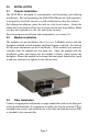
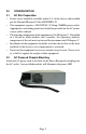
4.1 Media Converter Modules
The Media Converter Modules have LED indicators to provide information
on how the module is communicating to its link partner. The LED indicators
can also be used to troubleshoot problems with the connections.
LED Function Color OFF State ON State
Power "Pwr" Amber No Power On: Module has power
Fiber Port 1 duplex
"FDX"
Green
Fiber in Half Duplex
(when fiber link is active)
On: Full-Duplex
(when link fiber is active)
Fiber Port 1 link/activity
"Lk/Act"
Green No fiber link
On: Fiber link
Blinking: Fiber activity
Fiber Port 2 duplex
"FDX"
Green
Fiber in Half Duplex
(when fiber link is active)
On: Full-Duplex
(when link fiber is active)
Fiber Port 2 link/activity
"Lk/Act"
Green No fiber link
On: Fiber link
Blinking: Fiber activity
Media Converter Module LED Indicators
Page 7