FlexSwitchTM 8U Model 6500-FK Replacement Kit User Manual 140 Technology #500, Irvine, CA 92618 Phone: (949) 250-6510; Fax: (949) 250-6514
Table of Contents 1.0 1.1 2.0 2.1 2.2 2.4 3.0 3.1 3.2 3.3 3.3.1 4.0 4.1 5.0 INTRODUCTION .................................................................... 3 General Description ............................................................. 3 INSTALLATION ...................................................................... 3 Chassis Installation .............................................................. 3 Module Installation ...............................................................
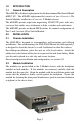
1.0 INTRODUCTION 1.1 General Description The 6500-FK is the direct replacement for the discontinued FlexSwitch Model 600XC 8U. The 6500-FK replacement kit consists of two iConverter 4Tx Switch Modules installed in a iConverter 2-Module chassis. The 6500-FK provides eight auto-negotiating 10/100 UTP ports with autocrossover that enables easy attachment to hubs, switches and workstations. The 6500-FK provides on-board DIP-Switches for manual configuration of Port 1 and 2 on each 4-Port Switch Module. 2.
2.4 UTP Installation Connect the UTP port via a Category 5 cable to a 10Base-T or 100Base-Tx Ethernet device. 3.0 CONFIGURATION 3.1 AC Site Preparation • Power source should be available within 5 ft. of the chassis and installed per the National Electrical Code ANSI/NFPA-70. • This equipment requires a 100-240VAC, 0.5Amp, 50/60Hz power outlet. Appropriate overloading protection should be provided on the AC power source outlets utilized.
3.3 Configuring the DIP-Switches The 6500-FK has been pre-configured with Auto-Negotiation enabled for plug and play easy of use. However, the iConverter Switch Modules offer additional configuration flexibility. 3.3.1 Switch Module Each 4-Port Switch Module has been pre-configured for Auto-Negotiation. On-board DIP-Switches are available to manually configure Port 1 and 2 of each module. The figure indicates the factory default settings.
is disabled when the UTP port is configured for manual negotiation. UTP 10/100Mbps “10/100” DIP-Switch (Port 1 or Port 2) When the UTP “AN/MAN” DIP-Switch (described above) is in the manual “MAN” position, the “10/100” DIP-Switch determines the speed of operation for the designated UTP port. Setting the “10/100” DIP-Switch to “100” position (factory default) forces the UTP port to operate at 100Mbps. Setting this DIPSwitch to “10” position forces the UTP port to operate at 10Mbps.
4.0 LED INDICATORS 4.1 Switch Module Each 4-Port Switch Module has LED indicators to provide connection information.
5.0 SPECIFICATIONS Description 8 Port 10/100 Auto-Sensing Switch Protocols 10Base-T, 100Base-Tx, with 1536 bytes max. frame size UTP Cable Type EIA/TIA 568A/B Category 5 and higher UTP Connector Type RJ45 DIP-Switches UTP Port 1 and 2: AN/MAN, 10/100, FDX/HDX Power Requirements 100 - 240 VAC @ 0.5A/0.4A, 50/60Hz Dimensions W:6.7" x D:5.51" x H:1.87" Weight 3.
the Internet at http://www.omnitron-systems.com. During the warranty period, Omnitron will, at its option, repair or replace a product which is proven to be defective. For warranty service, the product must be sent to an Omnitron designated facility, at Buyer’s expense. Omnitron will pay the shipping charge to return the product to Buyer’s designated US address using Omnitron’s standard shipping method.