SCAN A10 INSTRUCTIONS FOR INSTALLATION AND USE T es te d & L ist ed b y B ea v e r to n O r e g o n U SA O M N I-T e s t L a bo r a t o r ie s , In c. Save these instructions February 2003 KROG IVERSEN & CO.
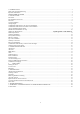
1. INTRODUCTION............................................................................................................................................................. 3 Safety and environmental testing. ......................................................................................................................................... 3 Important information: ............................................................................................................................................
We welcome you as a new owner of a SCAN A10 wood-burning stove. In purchasing a SCAN stove you have joined the growing ranks of concerned individuals whose selection of energy systems reflects both a concern for the environment and aesthetics. The SCAN stove is one of the finest home wood stoves in the world over. This manual will explain the installation, operation and maintenance of the SCAN A10 stove.
SAFETY PRECAUTIONS KEEP THE START DEVICE CLOSED DURING FIRING IN THIS STOVE. THE START DEVICE MAY BE OPENED FOR A MAXIMUM OF 5 MINUTES DURING START-UP. USE A METAL CONTAINER WITH A TIGHT FITTING LID TO DISPOSE OF ASHES. NEVER USE GASOLINE, GASOLINE-TYPE LANTERN FUEL, KEROSENE, CHARCOAL LIGHTER FLUID, OR SIMILAR LIQUIDS TO START OR “FRESHEN UP” A FIRE IN THIS STOVE. KEEP ALL SUCH LIQUIDS WELL AWAY FROM THE STOVE WHILE IT IS IN USE.
2. INSTALLATION Precaution If your SCAN A10 stove is not properly installed, operated and maintained, a house fire may result. For your safety, follow all installation, operation and maintenance directions. Contact your local building officials about restrictions and installation requirements in your area. Pre Installation Check List: Before you begin an installation, review your plans and check to see that: 1.
NOTE: The clearances expressed in inches are those approved for installation in the United States. The clearances in expressed in millimeters are those approved for installations in Canada. Different test standards for the respective countries may result in differences in the clearance requirements.
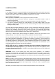
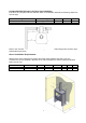
Corner installation Floor protection for Corner Installation A B C USA 16" 4” 69 5/8” Canada 457 1840 D 98 ½” 2602 In a rear vent installation the floor protection must also extend under the stovepipe a minimum of 2” (50mm) beyond either side of the pipe.
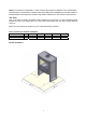
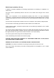
Combustible Wall Clearance for Top Vent Installation If the stove is to be placed at side and back walls of combustible materials the following clearances must be kept Parallel installation USA Connector pipe Single wall A 13” B 9.
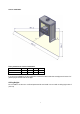
Combustible Wall Clearance for Rear Vent Installation If the stove is to be placed at side and back walls of combustible materials the following clearances must be kept: Rear outlet through wall USA Canada Connector pipe Single wall Single wall A 11" 280 B 6" 152 D 21" 533 Refer to the manufacturer’s instructions concerning installation of listed single wall connector pipe, wall thimble and chimney Alcove Installation Requirements: Whenever the stove is placed in a location where the ceiling height is
Mobile Home Installation: US only In addition to standard installation the following requirements are mandatory for installation in a mobile home. The stove must be permanently bolted to the floor of the mobile home using the floor screws provided. Note: If the composition of the manufactured (mobile) home floor is of light particleboard construction, you will be required to secure the stove with regular hex head bolts and nuts.
Outside air requirements Required for mobile home and in certain localities (Check with building officials) Outside air must not be drawn from an enclosed space (garage or other unventilated spaces) When using outside air, find a location where the chimney and outside air hole do not interfere with structural members of the home. Connect a 4" (100 mm) diameter stainless steel or other non-combustible corrosion resistant material, to the O.S.A hookup box.
Chimney Installation: Do not connect this unit to a chimney flue serving another appliance. Do not connect to any air distribution duct or system. The SCAN A10 stove is listed for installation as a vertically top or rear vented stove using a listed class A (UL103HT) for Canada (CAN/ULC-S629) factory built chimney exiting through the ceiling/attic/roof. The inside diameter of the chimney, connector pipe must not be smaller than 6” (152 cm) diameter. Single wall 24 gauge MSG (0.58 – 0.
Chimney Connection The chimney connector is ether a single or double walled pipe, depending on the type of installation, used to connect the stove to the chimney. For use with the SCAN woodstoves the chimney connector MUST be 6” in diameter, with a minimum thickness of 24 gauge black steel or 26 gauge blued steel. Aluminium and galvanized steel pipe is not acceptable for use with the SCAN woodstove.
Rear Vent Installation For venting into a masonry or a back standing steel chimney through the top vent the top horizontal portion of a single wall connector pipe can be located not closer than 18” below a combustible ceiling. From the factory the stove is prepared for top mounting of the flue collar, but all SCAN stoves have an optional flue outlet, therefore the flue collar can be fitted either on the top or at the rear as required. Mounting the flue collar for rear outlet: 1.
Combustible Wall Chimney Connector Pass-Throughs. Method A. 12” (304.8 mm) Clearance to Combustible Wall Member: Using a minimum thickness 3.5” (89 mm) brick and a 5/8” (15.9 mm) minimum wall thickness clay liner, construct a wall pass-through. The clay liner must conform to ASTM C315 (Standard Specification for Clay Fire Linings) or its equivalent. Keep a minimum of 12” (304.8 mm) of brick masonry between the clay liner and wall combustibles.
NOTES: 1. Connectors to a masonry chimney, excepting method B, shall extend in one continuous section through the wall pass-through system and the chimney wall, to but not past the inner flue liner face. 2. A chimney connector shall not pass through an attic or roof space, closet or similar concealed space, or a floor, or ceiling. Chimney height requirements: The chimney must extend 3 feet above the level of roof penetration and a minimum of 2 feet higher than any roof surface within 10 feet.
3. INSTRUCTIONS FOR USE Ash Drawer The ash drawer located behind the fuel door is designed to make cleaning easier by containing the ashes in a removable drawer Ash Grate Above the ash drawer, located in the floor of the firebox is a rotating ash grate to facilitate transferring ashes from the firebox into the ash drawer. To operate this grate, pull and push the handle under the bottom plate in and out several times. Operate stove only with the handle pushed all the way in.
Ceramic Packing Cord These stoves are equipped with a ceramic packing cord to ensure the tightness of the doors and the glasses. This packing cord is a wearing part and must be changed from time to time. Please consult your authorized dealer in this case. Protected Wall Reduced Clearances Local codes in some areas will allow reduced clearances when the stove is installed adjacent to a protected wall system. Your local building official must approve the variance.
Starting a Fire: Do not elevate the fire. Build fire directly on the hearth inside the stove; do not build fire above or in front of the log retainer. To start a fire: Pull the start device and air intake control to fully open. In addition, to help with the start-up, you may also leave the fuel door slightly ajar. Use a small amount of fire starters with enough kindling wood to establish a small, brisk fire.
Removing Baffle for Cleaning Be sure the fire is out and the stove is cold before removing baffle plate. Be cautions with handling the plates because the plates are made of a delicate material; which easily broke if not handle with care. Removal of the lower plate: lift the plate (pos 1) up from the supporting pins (pos 4) and take the pins out from the side plates (pos 10, pos 11) and take out the plate. Use the same procedure for the upper plate (pos 2) and take out plate.
Air Tube removal: Remove the screw (pos.1) on the left air tube collar (pos.3). Slide the air tube (pos.2) to the right, swing it down and remove it. Replacement Part List SCAN A10 Caution: Use only original SCAN A10 replacement part. Do not use substitute materials.
Creosote Formation and the Need for Removal When wood is burned slowly it produces tar and other organic vapors, which combine with expelled moisture to form creosote. The creosote vapors condense in the relatively cool chimney flue of a slow-burning fire. As a result, creosote residue accumulates in the flue lining. When ignited this creosote makes an extremely hot fire.
6. TROUBLESHOOTING Smoke: - Insufficient chimney draught! - Check if the chimney has the right dimension. - Check if the smoke pipe or chimney is blocked. - Check if the chimney has the right height compared to the surroundings. - Wood with excessive moisture content.
7. WARRANTY CONDITIONS FOR SCAN WOOD BURNING PRODUCTS All SCAN wood stoves, inserts and fireplaces are subject to a strict quality control, before they are shipped to the customer and end user. However, should an error occur, we back all SCAN wood burning stoves, inserts, and fireplaces with an extensive five years limited warranty. The warranty covers all parts that may require replacement from a failure that was caused in the judgment of SCAN, to be a defect in material or workmanship.
8.