CMK Wall Cable Management Installation Instructions Instrucciones de instalación Instructions d’installation Montageanleitung Istruzioni per l’installazione Installatie-instructies Инструкции по установке
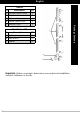
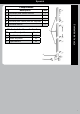
English Parts ID Description QTY 1 Straight Cable Covers 3 2 Clips 8 3 Adhesive Strips 8 4 Corner Cable Cover 1 5 Bottom Cover 2 2 ID Description 1 QTY A Wall Screw 16 B Wall Anchor 16 C Washer 16 3 4 5 Important: Before you begin, determine your preferred installation method: Adhesive or Screw Package Contents Hardware Kit
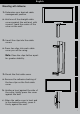
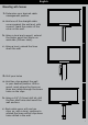
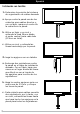
English Mounting with Adhesive 1: Determine your desired cable management position a. Hold one of the straight cable Flat Panel 1 covers against the wall and, with a pencil, mark the center of the cover on the wall. Installation Instructions 2: Insert the clips into the cable Installation Instructions covers a. Press two clips into each cable cover you will be using. Note: Place the clips farther apart 2 for greater stability. 3: Mount the first cable cover a.
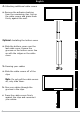
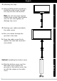
English 4: Attaching additional cable covers a. Remove the adhesive backing from the remaining clips, line up the cable covers and press them firmly against the wall. Flat Panel 4 Optional: Installing the bottom cover a. Slide the bottom cover over the Optional last cable cover. Ensure the grooves on the bottom cover line up with the ridges on the cable cover. 5: Running your cables a. Slide the cable covers off of the clips. Note: Do not pull the cable covers off, only slide them.
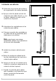
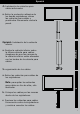
English Mounting with Screws 1: Determine your desired cable management position a. Hold one of the straight cable covers against the wall and, with a pencil, mark the center of the cover on the wall. Flat Panel b. Using a level and a pencil, extend the center point line 56mm on each side (112mm total). Installation Instructions 1 Installation Instructions c. Using a level, extend the lines down the wall. Flat Panel 2: Drill your holes a. Hold two clips against the wall in your desired position.
English 3: Attaching the clips a. Using a Phillips head screwdriver, thread the wall screws through the clips into the wall anchors. Flat Panel 3 Note: Do not use power tools to install these screws. Hand tighten only. Do not over tighten, as damage may occur. 4: Running your cables and attach the cable covers a. Run your cables through the grooves in the clips. b. Press the cable covers firmly 4 against the clips and reconnect your cables.
Spanish Componentes ID Descripción Cant. Cubiertas para cables directos 3 2 Sujetadores 8 3 Tiras adhesivas 8 4 Cubierta para cables para las esquinas 1 5 Cubierta inferior 2 Kit de instalación embolsado ID A Descripción Tornillos de pared 1 Cant.
Spanish Instalación con adhesivo 1: Determine la posición del sistema de organización de cables deseada a. Apoye contra la pared una de las Flat Panel 1 cubiertas para cable directo y, con un lápiz, marque el centro de la cubierta en la pared. 2: Introduzca los sujetadores en las cubiertas para cables a. Coloque a presión dos sujetadores en cada una de las cubiertas para cables que va a utilizar. Nota: para lograr una mayor 2 estabilidad, ubique los sujetadores de forma más separada.
Spanish 4: Instalación de cubiertas para cables adicionales a. Retire la protección adhesiva de Flat Panel 4 los demás sujetadores, alinee las cubiertas para cables y presiónelas firmemente contra la pared. Opcional: Instalación de la cubierta inferior Opcional a. Deslice la cubierta inferior sobre la última cubierta para cables. Asegúrese de que las ranuras de la cubierta inferior estén alineadas con los bordes de la cubierta para cables. 5: organización de los cables a.
Spanish Instalación con tornillos 1: Determine la posición del sistema de organización de cables deseada a. Apoye contra la pared una de las cubiertas para cables directos y, con un lápiz, marque el centro de la cubierta en la pared. Flat Panel b. Utilice un lápiz y un nivel y 1 extienda la línea 56mm desde el punto central hacia cada lado (112mm en total). c. Utilice un nivel y extienda las líneas hacia abajo por la pared. Flat Panel 2: haga los agujeros con un taladro a.
Spanish 3: instalación de los sujetadores a. Con un destornillador Phillips, enrosque los tornillos de pared a través de los sujetadores y hasta los tacos de pared. Flat Panel 3 Nota: no utilice herramientas mecánicas para instalar estos tornillos. Apriételos sólo con la mano. No apriete de más los tornillos porque podrían dañarse. 4: organización de los cables e instalación de las cubiertas para cables a. Coloque los cables por las ranuras dentro de los sujetadores.
French Pièces N° Description Qté Couvre-câbles droits 3 2 Clips 8 3 Bandes adhésives 8 4 Couvre-câbles de coin 1 5 Cache inférieur 2 2 Kit de matériel en sachet N° Description 1 Qté A Vis murales 16 B Chevilles d’ancrage mural 16 C Entretoises 16 4 5 12 3 Contenu de la boîte 1
French Montage avec adhésif 1: Déterminez la position désirée du dispositif de gestion des câbles. a. Tenez l’un des couvre-câbles Flat Panel 1 droits contre le mur et, avec un crayon, marquez l’emplacement du centre du cache sur le mur. Installation Instructions 2: Insérez les clips dans les couvre-câbles Installation Instructions a. Enfoncez deux clips dans chaque couvre-câble que vous utiliserez. Remarque: Pour une meilleure stabilité, espacez bien les clips.
French 4: Installez les autres couvre-câbles a. Enlevez la pellicule sur la surface adhésive derrière les autres clips, alignez les couvre-câbles et appuyez fermement contre le mur. Flat Panel 4 Facultatif : Installation du cache inférieur a. Faites glisser le cache inférieur sur Facultatif le dernier couvre-câbles. Assurezvous que les rainures du cache inférieur sont alignées avec les moulures sur le couvre‑câbles. 5: Passez les câbles a. Séparez les couvre-câbles de leurs clips.
French Montage avec vis 1: Déterminez la position désirée du dispositif de gestion des câbles. a. Tenez l’un des couvre-câbles droits contre le mur et, avec un crayon, marquez l’emplacement du centre du cache sur le mur. Flat Panel b. Avec un niveau et un crayon, Installation Instructions Installation Instructions 1 tracez une ligne parallèle à 56 mm de chaque côté de la ligne centrale (largeur totale 112 mm). c. Avec un niveau, prolongez les lignes en descendant sur le mur.
French 3 : Installez les clips a. Avec un tournevis à pointe cruciforme, vissez les vis murales dans les clips et dans les chevilles d’ancrage. Flat Panel 3 Remarque : N’installez pas ces vis avec un outil électrique. Serrez uniquement avec les doigts. Évitez de trop serrer. Vous pourriez causer des dommages. 4 : Passez les câbles et fixez les couvre-câbles a. Faites passer les câbles dans les rainures des clips. Flat Panel b.
Dutch Onderdelen Beschrijving Aantal 1 Rechte kabelafdekkingen 3 2 Klemmen 8 3 Klevende strips 8 4 Hoek kabelafdekking 1 5 Onderste afdekking 2 2 Zakje met bevestigingsmiddelen ID Beschrijving 1 Aantal A Wandschroeven 16 B Wandankers 16 C Afstandhouders 16 3 Inhoud van de doos ID 4 5 17
Language Dutch Kleefbevestiging 1: Bepaal de gewenste positie voor de kabelgoot a. Hou één van de rechte Flat Panel 1 kabelafdekkingen tegen de wand en teken met een potlood het midden van de afdekking af op de wand. 2: Steek de klemmen in de kabelafdekkingen a. Duw twee klemmen in elke kabelafdekking die u wenst te gebruiken. 2 Opmerking: Plaats de klemmen verder uit elkaar voor meer stabiliteit. 3: Bevestig de eerste kabelafdekking a.
Dutch 4: Bijkomende kabelafdekkingen bevestigen a. Verwijder de klevende rug van Flat Panel 4 de andere klemmen, lijn de kabelafdekkingen uit en druk ze stevig tegen de wand. Optioneel: De onderste afdekking installeren a. Schuif de onderste afdekking Optioneel over de laatste kabelafdekking. Zorg ervoor dat de groeven in de onderste afdekking uitgelijnd zijn t.o.v. de randen op de kabelafdekking. 5: Kabels aanbrengen a. Schuif de kabelafdekkingen van de klemmen.
Dutch Schroefmontage 1: Bepaal de gewenste positie voor de kabelgoot a. Hou één van de rechte kabelafdekkingen tegen de wand en teken met een potlood het midden van de afdekking af op de wand. Flat Panel b. Gebruik een waterpas en een 1 potlood en trek de middenpuntlijn aan elke zijde 56 mm door (in totaal dus 112 mm). c. Gebruik een waterpas om de lijnen langs de wand te verlengen. Flat Panel 2: Boor de gaten a. Hou twee klemmen in de gewenste positie tegen de wand.
Dutch 3: Klemmen bevestigen a. Gebruik een Phillips- schroevendraaier en draai de wandschroeven doorheen de klemmen in de wandankers. Flat Panel 3 Opmerking: Gebruik geen elektrisch gereedschap om deze schroeven te installeren. Draai ze enkel met de hand aan. Niet te hard aandraaien, anders kan er schade optreden. 4: Kabels plaatsen en kabelafdekkingen bevestigen a. Steek de kabels door de groeven in de klemmen. tegen de klemmen en sluit de kabels opnieuw aan. 4 b.
German Teile ID Beschreibung Menge 1 Gerade Kabelabdeckungen 3 2 Klemmschellen 8 3 Klebestreifen 8 4 Kabelabdeckung für Ecke 1 5 Untere Abdeckung 2 2 Befestigungssatz Beschreibung 1 Menge A Wandschrauben 16 B Dübel 16 C Unterlegscheiben 16 4 5 22 3 Inhalt ID
German Selbsthaftende Befestigung 1: Legen Sie die gewünschte Position der Kabelführung fest. a. Halten Sie eine der geraden 2: Fügen Sie die Klemmschellen in die Kabelabdeckung ein. Flat Panel 1 Kabelabdeckungen gegen die Wand und markieren Sie mit einem Bleistift die Mitte der Abdeckung an der Wand. Installation Instructions Installation Instructions a. Stecken Sie in jede Kabelabdeckung, die Sie verwenden, zwei Klemmschellen.
German 4: Zusätzliche Kabelabdeckungen befestigen a. Entfernen Sie die Klebeflächen von Flat Panel 4 den verbleibenden Abdeckungen, richten Sie die Kabelabdeckungen aus und drücken Sie sie fest gegen die Wand. Optional: Untere Abdeckung montieren a. Schieben Sie die untere Optional Abdeckung über die letzte Kabelabdeckung. Stellen Sie sicher, dass die Nuten der unteren Abdeckung an den Graten der Kabelabdeckung ausgerichtet sind. 5: Kabel verlegen a.
German Eingeschraubte Befestigung 1: Legen Sie die gewünschte Position der Kabelführung fest. a. Halten Sie eine der geraden Kabelabdeckungen gegen die Wand und markieren Sie mit einem Bleistift die Mitte der Abdeckung an der Wand. b. Verwenden Sie eine Wasserwaage Installation Instructions Installation Instructions 1 und einen Bleistift und verlängern Sie die Mittelachse an der Wand auf jeder Seite um 56mm (insgesamt 112mm). Flat Panel c.
German 3: Klemmschellen befestigen a. Drehen Sie mit einem Kreuzschlitzschraubenzieher die Schrauben durch die Klemmschellen in die Dübel. Flat Panel 3 Hinweis: Verwenden Sie zum Festziehen dieser Schrauben keine Elektrowerkzeuge. Ziehen Sie sie nur mit der Hand fest. Ziehen Sie die Schrauben nicht zu fest an, weil dadurch Schäden entstehen könnten. 4: Kabel führen und Kabelabdeckungen befestigen a. Führen Sie die Kabel durch die Flat Panel Schlitze in den Klemmschellen. 4 b.
Italian Parti ID Descrizione Qtà 1 Copricavi dritti 3 2 Fermagli 8 3 Strisce adesive 8 4 Copricavi angolari 1 5 Coperchio inferiore 2 2 ID Descrizione 1 Qtà A Viti da muro 16 B Tasselli per muratura 16 C Distanziatori 16 3 Componenti Ferramenta contenute nel sacchetto 4 5 27
Italian Montaggio con adesivo 1. Determinazione della posizione desiderata per il passacavi a. Posizionare uno dei copricavi Flat Panel 1 dritti contro la parete e, con una matita, segnare il centro del copricavo sulla parete. 2. Inserimento dei fermagli nei copricavi a. Premere due fermagli in ogni copricavo che verrà utilizzato. Nota: per maggior stabilità, 2 distanziare maggiormente i fermagli. 3. Montaggio del primo copricavi a. Rimuovere il copriadesivo dei due fermagli sul primo copricavo.
Italian 4. Montaggio di copricavi addizionali a. Rimuovere il copriadesivo dai fermagli rimanenti, allineare i copricavi e premere con forza contro la parete. Flat Panel 4 Facoltativo: installazione della copertura inferiore a. Far scorrere la copertura inferiore Facoltativo sull’ultimo copricavo. Accertarsi che le scanalature sulla copertura inferiore siano allineate con le nervature sul copricavo. 5. Inserimento dei cavi a. Far scorrere i copricavi fuori dai fermagli.
Italian Montaggio a vite 1: Determinazione della posizione desiderata per il passacavi a. Posizionare uno dei copricavi dritti contro la parete e, con una matita, segnare il centro del copricavo sulla parete. Flat Panel b. Dal punto contrassegnato, usare 1 una bolla ed estendere con la matita la riga centrale di circa 56 mm in ogni direzione (112 mm totali). c. Sempre utilizzando la bolla, estendere le linee verso il basso sulla parete. Flat Panel 2: Creazione dei fori a.
Italian 3: Montaggio dei fermagli a. Utilizzare un cacciavite con punta a croce per avvitare le viti attraverso i fermagli e nei tasselli. Flat Panel 3 Nota: non utilizzare attrezzi elettrici per serrare le viti. Serrare esclusivamente a mano. Per evitare danni, non stringere eccessivamente le viti . 4: Inserimento dei cavi e montaggio dei copricavi a. Far passare i cavi attraverso le scanalature nei fermagli. Flat Panel b. Premere fermamente i copricavi 4 sui fermagli e ricollegare i cavi.
Russian Поз. 1 2 3 4 5 Детали Описание Прямые кабельные накладки Кол-во 3 Скобы 2 8 Полосы с клейким покрытием 8 Угловая кабельная накладка 1 Нижняя крышка 2 Поз.
Russian Закрепление на клейкой основе 1. Определите место расположения кабельной разводки a. Прижмите одну из прямых кабельных Flat Panel 1 накладок к стене и карандашом отметьте положение центра накладки. Installation Instructions 2. Вставьте скобы в кабельные накладки Installation Instructions a. Вставьте две скобы в каждую накладку, которую планируется использовать. Примечание. Для большей 2 устойчивости расположите скобы на некотором расстоянии друг от друга. 3.
Russian 4. Закрепите дополнительные кабельные накладки a. Удалите пленку с клейкого покрытия Flat Panel 4 оставшихся скоб, выровняйте кабельные накладки и плотно прижмите их к стене. Дополнительный шаг: установка Дополнительный шаг нижней крышки a. Сдвиньте нижнюю крышку вдоль кабельной накладки, установленной последней. Для этого необходимо совместить канавки на нижней крышке с выступами кабельной накладки. 5. Уложите кабели a. Сдвиньте кабельные накладки со скоб. Примечание.
Russian Крепление на винтах 1. Определите место расположения кабельной разводки a. Прижмите одну из прямых кабельных накладок к стене и карандашом отметьте положение центра накладки. Flat Panel b. Используя уровень и карандаш, проведите центральную линию на 56 мм с каждой стороны (общая длина 112 мм). нижней части стены. Installation Instructions 1 c. Используя уровень, продлите линии до Installation Instructions Flat Panel 2. Просверлите отверстия a.
Russian 3. Закрепите скобы a. С помощью крестовой отвертки закрепите скобы на стене, завернув саморезы в дюбели. Flat Panel 3 Примечание. Саморезы следует заворачивать без применения электроинструментов. Выполняйте эту операцию только вручную. Во избежание повреждения инструментов не прикладывайте излишние усилия при затягивании винтов. 4. Уложите кабели и закрепите кабельные накладки a. Уложите кабели в канавки, расположенные на скобах. к скобам и подключите кабели к оборудованию.
English What Does This Warranty Cover? This warranty covers OmniMount Products against defects in materials and workmanship. This warranty only applies to products that are sold by an authorized OmniMount Dealer, and that reside within the United States. How Long Does This Coverage Last? This warranty covers your OmniMount Product for a period of 2 years. the defective component or product, at its sole discretion.
Dutch Specificaties zijn onderhevig aan wijzigingen zonder voorafgaande verwittiging. Alle inspanningen werden geleverd om een nauwkeurige en foutenvrije montage en installatie te leveren. OmniMount Systems wijst elke aansprakeli- jkheid af voor moeilijkheden die voortkomen uit de interpretatie van de informatie in deze instructies.
Thank You for purchasing an OmniMount Product. Gracias por adquirir un producto de OmniMount Merci d’avoir acheté un produit OmniMount Wie danken Ihnen, dass Sie ein OmniMount-Produkt erworben haben Grazie per aver preferito un prodotto OmniMount Dank u voor uw aankoop van een OmniMount-product Благодарим Вас за приобретение изделия OmniMount! OmniMount Systems, Inc. 8201 South 48th Street Phoenix, AZ 85044-5355 www.omnimount.com 800.668.