
User Manual


Page 2 of 2
Rev 1/11 SB
For Technical Assistance Contact:
Phone: 1-800-449-6649
OMIX-ADA Tech Support
E-mail: techsupport@omix-ada.com
Web: www.Omix-Ada.com
17265.01
All L. E. D.’s o- System is o and in factory mode.
Green L. E. D. on- System is on (Normal mode). Starts and runs with main battery. Charges both batteries with
ignition on.
Red L. E. D. on- System is on (Emergency mode). Both batteries are connected. Joins both batteries for
Starting or Winching when main battery is dead or vehicle motor is inoperative.
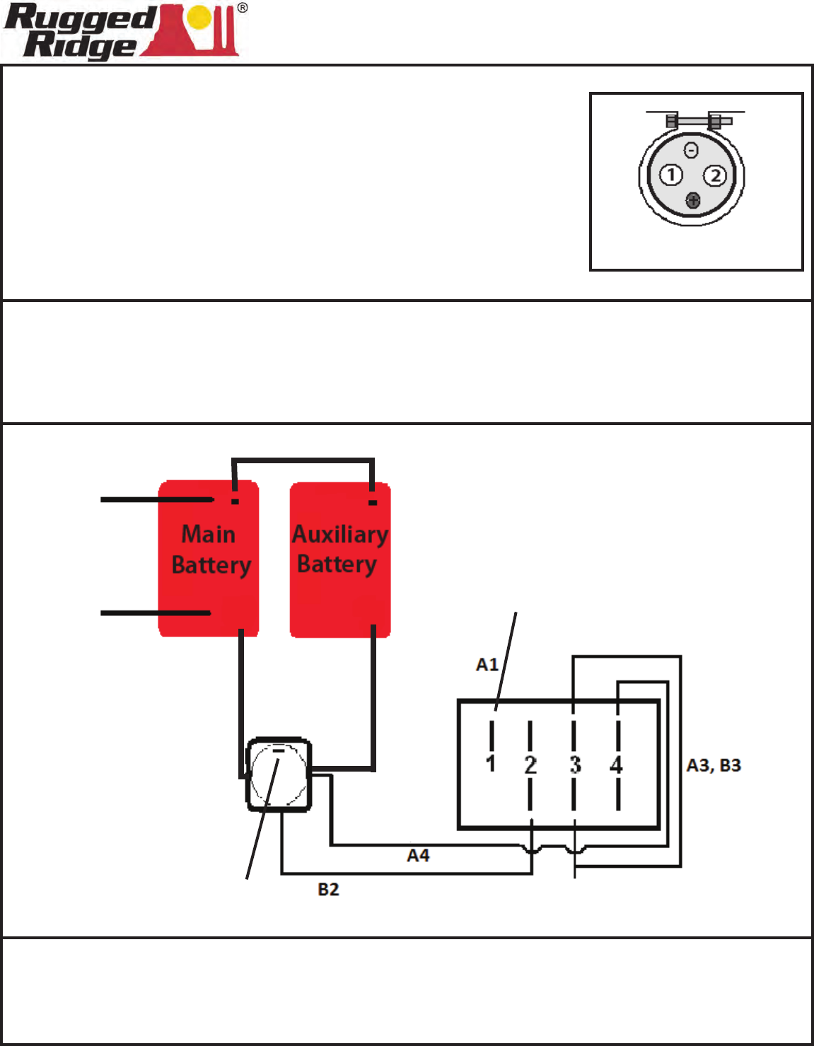
Step 4. Wiring the Isolator Relay. Connect the small (-) wire to the small (-)
position post on the relay, connect the opposite end to a chassis
ground. Connect the short (-) cable to the auxiliary battery using the
supplied (-) battery clamp, connect the opposite end to the main
battery negative clamp. Tighten and secure both (-) clamps. Connect
one of the long (+) cables to the auxiliary battery using the supplied
(+) battery clamp, connect the opposite end to the #2 position post on
the relay. Connect the other (+) cable to the #1 position post on the
relay, connect the other end to the (+) on the main battery. Tighten
and secure all (+) connections. Check all wires to ensure the do not
touch any hot or sharp surfaces. Test the system for proper function.
ISOLATOR
RELAY
(-) Negative Jumper
+
+
+
1 2
ISOLATOR
RELAY
(-) Negative
From Vehicle
(+) Positive
From Vehicle
(+) Positive
To Battery
(Main)
(+) Positive
To Battery
(Aux)
(+) Positive
To Relay
(+) Positive
To Relay
(-) Negative
Connect To Chassis
Ground
(-) Negative
Connect To Chassis
Ground
SWITCH
(+) Positive
Connect to a Switched
12 Volt Source
A
B