
User Manual


17265.01
DUAL BATTERY ISOLATOR KIT
PLEASE READ AND UNDERSTAND ALL INSTRUCTIONS BEFORE YOU BEGIN
SB
REV 1/11
Page 1 of 2
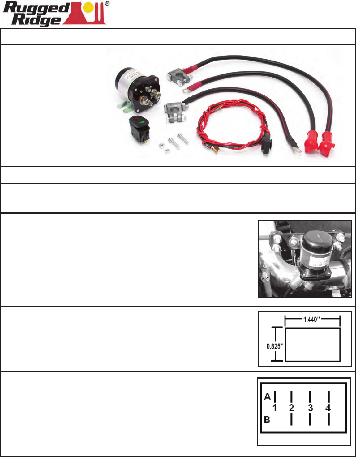
Step 1. Mount the Dual Battery Isolator.
When using Rugged Ridge Dual Battery Trays use the following locations:
CJ-(76-86), YJ-(87-95) Mount the Isolator to the battery hold down bar.
TJ-(97-06) Mount the Isolator to the bracket on the radiator core support
rod (As shown).
JK-(2007+Up) Mount the Isolator to the battery tray below the evap
solenoid.
When not used with a Rugged Ridge Dual Battery Tray you will need to
nd a suitable secure mounting location.
Step 2. Mount the Rocker switch in a suitable location.* The switch requires a
square mounting hole cut to the dimensions provided in the illustration.
*Rugged Ridge switch housing are available. Sold separately.
Kit Contents:
1. Isolator Relay
2. Dual position switch
3. Switch wiring harness
4. (+) Battery post clamp
5. (-) Battery post clamp
6. Battery cables (3)
7. Relay mounting hardware
Notice: Safety glasses, gloves and protective clothing should be worn when working around batteries.
Disconnect cables from the battery before you begin.
Step 3. Wiring the switch. Connect one end of the supplied ground wire to
terminal A1 and the other end to a good chassis ground. Connect one
of the long red wires from terminal A4 to the #2 post on the Isolator
Relay. Connect one of the long red wires from terminal B2 to the (+)
post on the relay. Locate the supplied wire with the inline fuse, connect
the end of the wire with 2 spade terminals to the A3 and B3 terminals on
the switch. Connect the other wire to a switched positive lead that only
has power when the ignition key is in the on position.
See diagram on page 2 for further wiring information.
Switch Terminal Diagram