
User's Manual


Setup Procedure
10
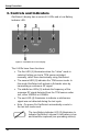
3. Controls and Indicators
OmiDetect’s display has a series of 6 LEDs and a Low Battery
Indicator LED.
Figure 2. OmiDetect 50's LED Display.
The 6 LEDs have three functions:
The first LED (1) illuminates when the “Listen” mode is
selected, letting you test a TPM sensor activated
manually, rather than electronically using OmiDetect.
The second LED (2) indicates the TPM sensor mode. In
this mode OmiDetect will activate a Schrader valve by
transmitting a continuous RF signal.
The middle two LEDs (3) indicate the frequency of the
response RF signal detected from the TPM sensor under
test, either 315MHz or 433MHz.
The next LED (4) illuminates to indicate a valid sensor
signal was not detected during the test cycle.
Note : On power On OmiDetect automatically reverts to
the last test mode used.
The Low Battery Indicator LED (5) illuminates to
indicate OmiDetect’s internal 9 volt battery is low
and should be replaced (see preceding section).