User’s Guide Shop online at omega.com ® ® www.omega.com e-mail: info@omega.
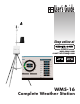
INTRODUCTION disk for permanent storage using the options available on the main menu. Congratulations on your purchase of a WMS-16 Weather Station, and welcome to the world of modular, user friendly weather data collection. The WMS-16 has been carefully designed with the user in mind, and we are confident that it will provide you with convenient and accurate weather data for years to come.
Barometric Pressure Barometric pressure is sensed using a piezoresistive sensing element. This element responds to changes in barometric pressure with a corresponding change in resistance. This resistance is converted to a voltage from which the microprocessor calculates the barometric pressure at the elevation at which the barometer is located. Since air pressure varies with elevation, the barometric pressure must be set for the elevation at which the barometer is installed.
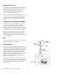
Figure 1 INSTALLATION Installation Considerations Installation of the WMS-16 is simple and straight forward, thanks to its modular design and terminal-strip connections. Figure 1 shows the control module’s rear panel and the locations of the various connections. An auxiliary battery can be used as an alternative power input if you do not intend to use the provided wall transformer.
Tripod Tower RS-232 Interface The five foot tripod tower provided for the WMS-16 is constructed of steel tubing for durability and strength. Horizontal bracing is a feature of the tripod tower. The tower’s foot brackets can be bolted onto a concrete foundation or a wooden platform. The wind speed and direction sensor mounts on top of the mast. The solar radiation shield with 6” mast and coupling are made to clamp on the five-foot aluminum mast.
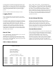
Sensor Installation 5.Temperature 6.Temperature 7.Wind Direction Install the sensors in their chosen locations, bearing in mind the installation considerations noted earlier. Run cables from the sensors to the control module location, with no cable exceeding the maximum allowable length listed in Table 1. WMS-16T WMS-16T WMS-02 A5 A6 A7 Add sensor [A], delete sensor [D], or quit [Q]: When the sensors have been installed and the cables run, connect and test them as described in the following sections.
While watching the main screen, slowly turn the offset adjustment screw. Clockwise will decrease the pressure reading. You may have to turn the adjustment 3 to 10 revolutions before the display starts to change. Turn the pot slowly in single turn increments, then wait for the screen to update, every five seconds. If the value is moving away from the correct value obtained above, turn the screw in the opposite direction.
Handshaking Xon/Xoff Once the main menu is present proceed with the station setup procedures as described in the next section. Station Setup Press “Esc” to get to the main menu. Press “1” at the main menu to initiate the Station Setup procedure. This procedure allows you to specify certain operational parameters that the WMS-16 uses in its calculations and on its display. Run Station Setup when using the weather station for the first time.
averaging period is less than the logging period the average logged will be for a period of time at the end of the logging period equal to the averaging period. If the averaging period is longer than the logging period then the data stored will be a running average that reaches back in to previous logging periods. Enter the number of minutes desired and press “Enter”. Logging Period Press 4. Logging Period. The menu will ask you to enter a number between 1 and 60 minutes.
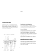
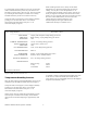
Figure 7 Row and Column Presentation of Current Data you wish to view more than a full day’s data, or fractions of days (two-and-a-half days), chose the selection, “4” Display Log by Days, retrieves data in daily blocks with a minimum retrievable block of one full day’s data. After selecting “3” from the main menu, specify the number of hours of data to be retrieved. The data will be displayed in the format shown in Figure 8.
not, hover, return to a previous screen, you must return to the main menu and begin the retrieval procedure anew. If you want to further manipulate or obtain a printed copy follow the procedure described in the Data Download section below. Enter number of hours to view: 1 DATE TIME WS PK WD T1 T2 RH BP RF SR M/D H:M mph mph deg F F % inHg in W/m^2 ============================================================================= 02/01 15:18 0.7 2.1 318 +57.2 +0.0 56 29.32 0.00 0 02/01 15:19 0.1 0.6 329 +57.
Ø If you want to further manipulate or obtain a printed copy follow the procedure described in the Data Download section below. Ø Data Download Ø Selection “5” on the main menu “Data download” – allows you to save a permanent record of the WMS-16’s stored data. The data retrieval procedure is dependent on the communications software program used.
Enter the type of alarm function you wish to use Exclusive (Alarm switch is closed when the reported sensor value is outside of the low and high values selected.) or Inclusive (Alarm switch is closed when the reported sensor value is between the low and high values selected.). Enter Output: A1 [1] or A2 [2]. Enter low threshold. Enter high threshold. Enter on delay in seconds [0-1200]. It is the time that the sensor value is in the alarm condition before the alarm switch activates.
to always have DCD on. The modem is then plugged into a telephone line and it is ready to be called from a remote location. In order to call the WMS-16 from a remote computer the computer needs to have a communications program such as HyperTerminal or Procom. The communications parameters for the communications program are ASI, 9600, 8-N-1. When the computer calls the WMS-16, the WMS-16’s modem will go off-hook and the WMS-16, will begin transmitting to the remote computer.
Sensor type Model Wind Speed WS-01/02 Input Calibration P1 If you intend to add another sensor select A. If you do not want to add another sensor select Q. You will be asked if you are sure that you want to erase memory. If you have added or deleted a sensor select Y if not select N and press ENTER. To initialize the Wind Direction sensor Press EXC to get the MAIN MENU. From the MAIN MENU press number 1. STATION SET UP Then press ENTER From the Station Set up menu press number 6.
From the Station Set Up menu press number 6. ADD OR REMOVE SENSORS. Then press Y, then ENTER. From the Sensor Type Menu select number 4. Temperature. Then press ENTER. From the Temperature Sensors Menu select number 1. (WMS-16T). Then press ENTER. The menu then asks: Enter temperature offset or press Q to quit. Press Q. From the Sensor Input Channel Menu select number 9. A5. Then press ENTER. If you intend to add another sensor select A. If you do not want to add another sensor select Q.
From the Station Set Up menu press number 6. ADD OR REMOVE SENSORS. Then press Y, then ENTER. From the Sensor Type menu select number 6. (Pressure). Then press ENTER. From the Pressure Sensors menu select number 1. (WMS-16BP). Then press ENTER. The menu asks: Enter pressure offset or press Q to quit. Press Q. Pressure WMS-16BP A2 If you intend to add another sensor select A. If you do not want to add another sensor select Q. You will be asked if you are sure that you want to erase memory.
The auxiliary temperature sensor is a thermistor attached to a two conductor cable. Connect one conductor to A5 terminal and the other conductor to a GROUND terminal. INITIALIZATION OF THE AUXILIARY TEMPERATURE SENSOR. Press EXC to get the MAIN MENU. From the MAIN MENU press number 1. STATION SET UP. From the Station Set Up menu press number 6. ADD OR REMOVE SENSORS. Then press Y, then ENTER. From the Sensor Type Menu select number 4. Temperature. Then press ENTER.
Then select Channel A2.
Options: WMS-16SR WMS-16T WMS-16TWS RG-2501/40 WMS-16PE Solar Radiation Sensor, includes mounting arm and 40' cable Auxiliary Air Temperature Sensor, 40’ Cable Water or Soil Temperature Sensor, 40’ Cable Tipping Bucket Rain Gauge, 40’ Cable Power Supply 220 VAC WMS-ENCL-16A NEMA-4X Enclosure Assembly, includes mounting brackets, 12V 7AH battery and 10 watt solar panel battery charger WMS-ENCL-16B NEMA-4X Enclosure Assembly, includes mounting brackets, 12V 7AH battery and 110Vac/60Hz battery charger WMS-16
Where Do I Find Everything I Need for Process Measurement and Control? OMEGA…Of Course! Shop online at www.omega.
omega.com ® ® OMEGAnet ® Online Service www.omega.com Internet e-mail info@omega.com Servicing North America: USA: ISO 9001 Certified Canada: One Omega Drive, P.O. Box 4047 Stamford CT 06907-0047 TEL: (203) 359-1660 e-mail: info@omega.com 976 Bergar Laval (Quebec) H7L 5A1 TEL: (514) 856-6928 e-mail: info@omega.
MADE IN USA WARRANTY/DISCLAIMER OMEGA ENGINEERING, INC. warrants this unit to be free of defects in materials and workmanship for a period of 13 months from date of purchase. OMEGA’s WARRANTY adds an additional one (1) month grace period to the normal one (1) year product warranty to cover handling and shipping time. This ensures that OMEGA’s customers receive maximum coverage on each product. If the unit malfunctions, it must be returned to the factory for evaluation.