
Owner's manual


Chapter 4: PowerDAQ Software
56
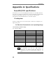
Counter/Timer Subsystem
Counter/timer subsystem has three 24-bit counters, and common 20-
bit optionally used divider called pre-scaler. Each counter has a set of
it’s own load/count/status and compare registers. Please refer to the
example sources and Motorola DSP56301 DSP user manual (Motorola
PN DSP565301UM) for the details about DSP counter/timer
programming.
Counters named TMR0, TMR1 and TMR2. Each timer can use internal
or external clocking and can interrupt the DSP56301 after a specified
number of events (clocks) or can signal an external device after
counting internal events. Each timer connects to the external world
through a single bi-directional pin TIOx that is 7kV ESD and +/-30V
overvoltage protected. When TIOx is configured as input the timer
functions as an external event counter or can measure external pulse
width/signal period. When TIO is used as output the timer is
functioning as either a timer, a watchdog or a Pulse Width Modulator.
Some common timer/counter/output functions which microprocessors
require are:
• Real time clock,
• Event counter
• Digital one-shot
• Programmable rate generator
• Square wave generator
• Binary rate multiplier
• Complex digital wave form generator
• Complex motor control
DSP Counter/timers are used by –ST and –CT boards to define a time-
base for input and output streamed operations. TMR1 counter is used
for the buffered input modes such as buffered digital input and
buffered counter-timer external event streaming. TMR2 is a time-base
for the digital output buffered mode. TMR0 and/or TMR1 may be also
a source (counters, counting events) for the counter stream operation
on the –CT board.