
Owner's manual


Chapter 4: PowerDAQ Software
54
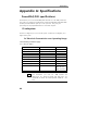
Enhanced Serial Interfaces (ESSI)
Basically ESSI port has input and output data lines, input and output
clock lines and input and output frame synchronization lines. Frame is 1
to 32 data words. Data word length is 8/12/16/24 and 32 bits. 32-bit
mode doesn’t use either most or least significant byte (MSB/LSB). Also
operational mode includes normal and network modes. Network mode
adds one extra bit clock after every frame for the synchronization. The
I/O and clock polarity is programmable via the software.
PowerDAQ SDK provides two access levels to the ESSI ports.
Easiest way is to program ESSI registers directly using the DSP access
functions:
PdDSPRegRead and PdDSPRegWrite. PowerDAQ SDK provide
set of necessary constants and complete example essi_
io.c which
shows how to access ESSI port on this level. This mode does not
support interrupts – user application must pull readiness bits in the ESSI
registers to insure the data transfer integrity.
The second way is to use limited buffered ESSI0 support, which is
provided by the high-level PowerDAQ SDK functions. In this case
transfer speeds up to 1.05Mword/sec supported which leads to
16.5Mbit/s ESSI bit rate. In this mode TX0 output and RX0 inputs with
full clock and frame synchronization supported. TX and RX subsystems
are semi-independent and may be used simultaneously.
Note TX subsystem in buffered mode shares some
resources with digital output in buffered mode and
they are mutually exclusive. The same is true for the
RX subsystem and digital input or counter-timer
event input modes. Thus, when you decide to use
ESSI subsystem on the –ST or –CT boards, please
make sure that you are not creating a conflict with
the existing software.
Note PD-DIO-CBL-26 or equivalent must be used to
connect PDx-DIO board J4 connector to the PDx-
DIO-STP-64, when ESSI features are used.
Following examples are supplied with PowerDAQ SDK 3.x which
supports ESSI input/output buffered modes: