
Owner's manual

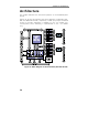
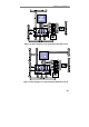


Chapter 3: Architecture
37
Note The drivers from the PowerDAQ web site always
contains the latest versions of the DSP firmware.
Please check www.Omega Engineeringdaq.com
for
the updates.
Note Custom programming of the DSP is not available
with the standard PowerDAQ DIO product. However,
should you require DSP processing, please consult
the factory.
PCI/PXI Bus Interface
The PowerDAQ DIO boards communicate via the PCI bus. The PCI bus
interface is embedded in the Motorola 56301 DSP. On power up, the
host PC automatically configures the boards’ base address and
interrupts resources.
PowerDAQ PDXI-DIO also incorporates support of PXI-TRIGx and
PXI_STAR lines according to PXI standard. Special software called PXI
Configurator supplied with PowerDAQ PDXI-DIO boards helps to
configure PXI bus. Also, all PXI configuration features are available via
the SDK function calls. Please note, that PXI configuration data is
stored into on-board EEPROM.
Digital Input and Output Subsystem (DIO)
The PowerDAQ digital input/output boards are configured as 64 or 128
(PD2-DIO only) lines. All boards use 16-bit line drivers, (not 8255
devices) which allow you to configure the start-up states in groups of
16-bit ports. Every port may be declared as input or output at start-up
and with user-defined default output value.
The DIO subsystem has different input modes, channel list options,
start and stop triggering and clocking control.
Also, every digital input may be configured to generate an interrupt on
any change of state on any line with edge detection. This is software
configurable.