
Owner's manual


Chapter 3: Architecture
36
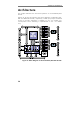
Functional Overview
All PowerDAQ DIO boards are based on the Motorola 56301 DSP with
full 32-bit 33MHz PCI support. All subsystems, except DIO are resides
on the DSP itself and accessible via PowerDAQ SDK functions. The DIO
subsystem is implemented as a set of 16-bit bi-directional registers with
overvoltage and ESD protection circuitry and pull-up resistors (PDL-DIO
and PDXI-DIO series only). Those registers are controlled by dedicated
logic that manages read/write access and provide direction control. DSP
is capable of monitoring all available input ports and interrupt host PC
on state change on any selected line with edge detection. Initial state
and direction of the DIO ports is programmed via software
(StartUpState program is supplied with PowerDAQ SDK) and stored in
the on-board EEPROM. It takes less, than 10mS after the system reset
to restore those values.
Following user subsystems are present on the DIO board:
• Digital Input
• Digital Output
• Counter-Timers
• Serial ESSI ports
• High-Speed Digital Interrupts
• Calibration/Startup configuration (EEPROM-based)
Difference between PD2-DIO and PDL-DIO boards is a board form-
factor (PDL-DIO is a half-size of PD2-DIO) and a connector used.
PDXI-DIO moved form-factor into the CompactPCI standard and adds a
PXI compatibility.
DSP Processor
All PowerDAQ PD2-DIO boards are based on the Motorola 56301 DSP.
This is a 24-bit 66 MHz processor with an integrated PCI interface. The
PCI interface implements the PCI Local Bus Specifications so the board
is fully auto configured (base address, interrupt)
When the PowerDAQ DIO software is loaded, the PowerDAQ DIO
firmware is downloaded to the DSP via the PCI bus. This firmware
contains all the code necessary to communicate with the board
subsystems and the host PC driver.