
Owner's manual


Chapter 2: Installation and Configuration
26
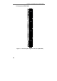
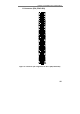
J4/J5 ESSI Connector (PD2-DIO)
Figure 9: Connector Pin Assignments for J4/5 (PD2-DIO)
Note J4/J5 Connector was designed to use either 26-way
IDC header for both ports or one 12-way IDC header
for the single port operations. For the combined
J4/J5 port the pin numbering is follows – 1..12 –
ESSI0 (J4), 13..14 – N/C, 15..26 – ESSI1(J5).
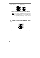
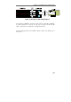
J3 Counter/Timers/IRQx Connector (PD2-
DIO)
Figure 10: Connector Pin Assignment for the J3 (PD2-DIO)