
Owner's manual


Chapter 2: Installation and Configuration
17
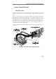
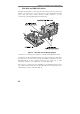
Hardware diagnostic procedure
Connect PowerDAQ DIO board to the screw terminal using the proper
cable (PD-DIO-CBL-100 for the PD2-DIO boards and PD-DIO-CBL-96
for all other models).
First thing you can measure is a presence of 5V power on the screw
terminal, which has 200mA maximum load capability (up to 1A option
is available, please contact factory for the details).
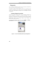
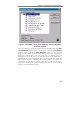
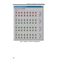
Also, you can attach the scope or logic analyzer to the certain I/Os, run
DIOTest application and check the output. The output of every enabled
channel should be seen as a positive pulse.
Subsystem- and application- specific examples
There are a numerous examples supplied with PowerDAQ SDK that
support PowerDAQ DIO boards. Please refer to readme file of the
latest installation and comments at the beginning of the main file of
each example you had installed for the details. Also, there is a
PowerDAQ Programming Manual available. That manual provides a
lot of detailed information about low level (C/C++) programming of
the PowerDAQ DIO boards and a numerous topics with general
information about PowerDAQ boards programming under the different
operating systems.
All PowerDAQ manuals are supplied in electronic Adobe Acrobat PDF
format. If you require the PDF reader, this can be downloaded from
the Internet at no cost from www.adobe.com
Following C/C++ examples are supplied with revision 3.x of PowerDAQ
SDK:
pddio_in.c - digital I/O single read example
pddio_ou.c - digital I/O single write example
pddi_buf.c - digital input stream (-ST boards only)
pdssi_ib.c - ESSI0 RX0 input stream
pddo_buf.c - digital output stream (-ST boards only)
pdssi_ob.c - ESSI0 TX0 output stream
pdct_evt.c - counter/timer events
pdct_buf.c - counter/timer (TMR0/TMR2) input stream (-CT only)