User’s Guide Shop online at www.omega.com e-mail: info@omega.
OMEGAnet ® Online Service www.omega.com Internet e-mail info@omega.com Servicing North America: USA: ISO 9001 Certified Canada: One Omega Drive, P.O. Box 4047 Stamford CT 06907-0047 TEL: (203) 359-1660 e-mail: info@omega.com 976 Bergar Laval (Quebec) H7L 5A1, Canada TEL: (514) 856-6928 e-mail: info@omega.
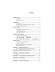
Contents INTRODUCTION..........................................................................1 OVERVIEW................................................................................................ 1 W HAT ’S INCLUDED ................................................................................ 1 CARD SETUP ..............................................................................2 CLOCK M ODES ........................................................................................
FEDERAL COMMUNICATIONS COMMISSION STATEMENT ............ 14 EMC DIRECTIVE STATEMENT ........................................................... 14 Figures Figure 1 - Clocking Mode ‘Divide By 4’............................................................2 Figure 2 - Clocking Mode ‘Divide By 1’............................................................2 Figure 3 - Asynchronous Communications Bit Diagram.............................
Introduction Introduction Overview The OMG-COMM8-PCI provides the PC with eight RS-232 asynchronous ports. The OMG-COMM8-PCI allows for connection to any device utilizing the RS-232 electrical interface, such as modems, data-entry terminals, and plotters. What’s Included The OMG-COMM8-PCI is shipped with the following items. If any of these items is missing or damaged, contact the supplier.
Card Setup Card Setup Clock Modes The OMG-COMM8-PCI employs a unique clocking option that allows the end user to select from divide by 4 and divide by 1 clocking modes. This mode is selected at J1. DIV1 DIV4 To select the Baud rates commonly associated with COM: ports (i.e. 2400, 4800, 9600, 19.2, … 115.2K Bps) place the jumper in the divide by 4 mode (silk-screen DIV4). Figure 1 - Clocking Mode ‘Divide By 4’ DIV1 DIV4 To select the maximum data rate (460.
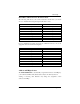
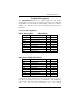
Card Setup Baud Rates and Divisors for the ‘Div1’ mode The following table shows some common data rates and the rates you should choose to match them if using the adapter in the ‘Div1’ mode. For this Data Rate 1200 bps 2400 bps 4800 bps 9600 bps 19.2K bps 57.6 K bps 115.2 K bps 230.4K bps 460.8K bps Choose this Data Rate 300 bps 600 bps 1200 bps 2400 bps 4800 bps 14.4K bps 28.8K bps 57.6 K bps 115.
Installation Installation Operating System Installation For Windows Users Start by choosing Install Software at the beginning of the CD. Choose Asynchronous COM: Port Software, SeaCOM. Other Operating Systems Refer to the appropriate section of the Serial Utilities Software. System Installation The OMG-COMM8-PCI can be installed in any of the PCI expansion slots and contains a single jumper strap that must be set for proper operation.
Technical Description Technical Description The OMG-COMM8-PCI utilizes the 16C554 UART. This chip features programmable baud rate, data format, interrupt control and a 16-byte input and output FIFO, and is functionally 4 16C550 UARTs. A full array of advanced UARTS is also available for this card. Contact Omega Engineering for more information.
Technical Description DB-78 Connector Pin Assignments Port # TD RD RTS CTS DTR DSR DCD RI GND OMG-COMM8-PCI 1 36 37 17 16 35 18 38 15 34 2 12 11 31 32 13 30 10 33 14 3 27 28 8 7 26 9 29 6 25 4 3 2 22 23 4 21 1 24 5 (DB78 FEMALE) 5 75 76 56 55 74 57 77 54 73 6 51 50 70 71 52 69 49 72 53 7 66 67 47 46 65 48 68 45 64 8 42 41 61 62 43 60 40 63 44 Page 6
Specifications Specifications Environmental Specifications Specification Temperature Range Humidity Range Operating 0º to 50º C (32º to 122º F) 10 to 90% R.H. Non-Condensing Storage -20º to 70º C (-4º to 158º F) 10 to 90% R.H. Non-Condensing Power Consumption Supply line Rating +12 VDC 60 mA -12 VDC 100 mA +5 VDC 295 mA Mean Time Between Failures (MTBF) Greater than 150,000 hours.
Appendix A - Troubleshooting Appendix A - Troubleshooting Serial Utility test software is supplied with the adapter and will be used in the troubleshooting procedures. By using this software and following these simple steps, most common problems can be eliminated without the need to call Technical Support. 1. Identify all I/O adapters currently installed in your system. This includes your on-board serial ports, controller cards, sound cards etc.
Appendix A - Troubleshooting PCI COM NUMBER SELECTION IN WINDOWS 95 When installing a multi-port PCI card in Windows 95 the default starting COM: number assigned to the first port will be COM:5 if no COM:5 exists. If there is a COM: 5, 6, etc., the next available COM: number will be assigned to the first port with all additional ports following in ascending order.
Appendix B - How To Get Assistance Appendix B - How To Get Assistance Please refer to Troubleshooting Guide prior to calling Technical Support. 1. Read this manual thoroughly before attempting to install the adapter in your system. 2. When calling for technical assistance, please have your user manual and current adapter settings. If possible, please have the adapter installed in a computer ready to run diagnostics. 3. Omega Engineering maintains a Home page on the Internet.
Appendix C - Electrical Interface Appendix C - Electrical Interface RS-232 Quite possibly the most widely used communication standard is RS-232. This implementation has been defined and revised several times and is often referred to as RS-232-C/D/E or EIA/TIA-232-C/D/E. It is defined as “Interface between Data Terminal Equipment and Data Circuit- Terminating Equipment Employing Serial Binary Data Interchange”. The mechanical implementation of RS-232 is on a 25-pin D sub connector.
Appendix D - Asynchronous Communications Appendix D - Asynchronous Communications Serial data communications implies that individual bits of a character are transmitted consecutively to a receiver that assembles the bits back into a character. Data rate, error checking, handshaking, and character framing (start/stop bits) are pre-defined and must correspond at both the transmitting and receiving ends.
Appendix E - Silk-Screen Appendix E - Silk-Screen 3.8" 5.650" 3.
Appendix F - Compliance Notices Appendix F - Compliance Notices Federal Communications Commission Statement FCC - This equipment has been tested and found to comply with the limits for Class A digital device, pursuant to Part 15 of the FCC Rules. These limits are designed to provide reasonable protection against harmful interference when the equipment is operated in a commercial environment.
WARRANTY/DISCLAIMER OMEGA ENGINEERING, INC. warrants this unit to be free of defects in materials and workmanship for a period of 13 months from date of purchase. OMEGA’s WARRANTY adds an additional one (1) month grace period to the normal one (1) year product warranty to cover handling and shipping time. This ensures that OMEGA’s customers receive maximum coverage on each product. If the unit malfunctions, it must be returned to the factory for evaluation.
Where Do I Find Everything I Need for Process Measurement and Control? OMEGA…Of Course! Shop online at www.omega.