
Products, Inc Computer Hardware User Manual


Configuration
OMG-USB-SER-4 Page 7
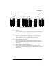
Switch Examples Continued
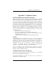
Port 4 Port 3 Port 2 Port 1
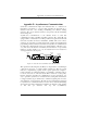
Figure 3: Electrical Interface Configuration
Port 1 : RS-232
The corresponding shunt is in the 232 position. The switches will have
no effect.
Port 2 : RS-485 two wire communication with no echo.
The corresponding shunt is in the 422/485 position. Switches 485 2,
NE 2, and Port 2 L, L, T, PU, and PD are all in the ON position.
Port 3 : RS-422 with 120 ohm termination.
The corresponding shunt is in the 422/485 position. Switches 485 3,
NE 3, and Port 2 L, L, PU, and PD are all in the OFF position, T is in the
ON position.
Port 4 : RS-485 two wire communication with echo.
The corresponding shunt is in the 422/485 position. Switches 485 4,
and Port 2 L, L, T, PU, and PD are all in the ON position, NE 4 is in the
OFF position.
RS 232
RS 232
RS 232 RS 232RS 422/485
RS 422/485 RS 422/485
RS 422/485
Port 3
L
L
T
PU
PD
ON
1 2 3 4 5 6 7 8
OFF
9 10
Port 4
L
L
T
PU
PD
ON
1 2 3 4 5 6 7 8
OFF
9 10
Port 1
L
L
T
PU
PD
Port 2
L
L
T
PU
PD
E1 E4E3E2
E5
E6
E7 E8
SW2
SW4