User’s Guide Shop online at www.omega.com e-mail: info@omega.
OMEGAnet ® Online Service www.omega.com Internet e-mail info@omega.com Servicing North America: USA: ISO 9001 Certified Canada: One Omega Drive, P.O. Box 4047 Stamford CT 06907-0047 TEL: (203) 359-1660 e-mail: info@omega.com 976 Bergar Laval (Quebec) H7L 5A1, Canada TEL: (514) 856-6928 e-mail: info@omega.
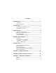
Contents INTRODUCTION..........................................................................1 OVERVIEW................................................................................................ 1 W HAT ’S INCLUDED ................................................................................ 1 INSTALLATION ..........................................................................2 OPERATING SYSTEM INSTALLATION ................................................. 2 SYSTEM INSTALLATION................
APPENDIX D - ASYNCHRONOUS COMMUNICATIONS ...............14 APPENDIX E - COMPLIANCE NOTICES .....................................15 FEDERAL COMMUNICATIONS COMMISSION STATEMENT ............ 15 CANADIAN RADIO INTERFERENCE REGULATIONS......................... 15 EMC DIRECTIVE STATEMENT ........................................................... 16 Figures: Figure 1: Switches SW2 and SW4.....................................................................5 Figure 2: RS422/485 Interface Configuration ...........
Introduction Introduction Overview The OMG-USB-SER-4 equips the PC with 4 USB to RS-232/422/485 Asynchronous serial ports providing a versatile interface for common serial needs. The advantage of this product over more traditional approaches is that it does not require opening the computer case, nor does it require resources such as I/O ports or IRQ’s. It does require a system that supports USB both in terms of hardware and operating system.
Installation Installation Operating System Installation Choose Install Software at the beginning of the CD and install SeaCOM. System Installation The screen captures below are taken from a Windows 98 installation. Your particular operating system may differ slightly from what is shown based on your version of Windows. The OMG-USB-SER-4 can be connected to any upstream type “A” port either at the PC host or an upstream hub.
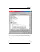
Installation You can access your new COM: ports by using the assigned COM: identifiers as shown above. In this case, it is COM3, 4, 5 and 6. However, this assignment will vary from system to system. At this point, the hardware is recognized and ready to use.
Configuration Configuration Original configuration This device ships with the following configuration. 422 mode, 120 ohm termination, 1K ohm pull up on RX+ 1K ohm pull down on RXIn order to change this configuration the box must be opened. Do this by removing the four screws located on the bottom. When reassembling please note that the top and bottom are keyed to fit in only one direction.
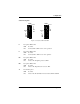
Configuration Switch Descriptions SW4 SW2 1 2 3 4 5 6 7 8 9 10 1 2 3 4 5 6 7 8 9 10 Port 2 L L T PU PD ON OFF ON OFF Port 4 L L T PU PD Port 3 L L T PU PD Port 1 L L T PU PD Figure 1: Switches SW2 and SW4 L 485 option, OFF for 422. OFF: No effect ON : Connects TX+ to RX+ for two-wire operation L 485 option, OFF for 422. OFF: No effect ON : Connects TX- to RX- for two-wire operation PU 485 option, OFF for 422.
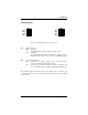
Configuration Switch Examples SW1 1 2 3 4 1 2 3 4 485 1 NE 1 485 2 NE 2 ON OFF ON OFF 485 3 NE 3 485 4 NE 4 SW3 Figure 2: RS422/485 Interface Configuration 485 Mode Selection OFF : 422 Mode The transmitter lines TX+ and TX- are always driven ON : 485 Mode The transmitter lines TX+ and TX- are switched to high impedance when the device is not actively transmitting data NE 485 option, OFF for 422 OFF : The receiver is always enabled.
Configuration Switch Examples Continued Port 4 Port 3 SW2 RS 232 RS 422/485 E4 Port 2 L L T PU PD E5 E6 ON E3 SW4 1 2 3 4 5 6 7 8 9 10 E2 Port 1 RS 232 RS 422/485 OFF 1 2 3 4 5 6 7 8 9 10 E1 ON OFF Port 4 L L T PU PD Port 2 RS 422/485 RS 232 Port 3 L L T PU PD RS 422/485 RS 232 Port 1 L L T PU PD E7 Figure 3: Electrical Interface Configuration Port 1 : RS-232 The corresponding shunt is in the 232 position. The switches will have no effect.
Technical Technical Description The OMG-USB-SER-4 utilizes four USB UARTs. These chips feature programmable baud rate, data format, 128 byte Dual Port TX Buffer, and 384 byte Dual Port RX Buffer. The RS-232/422/485 transceiver supports data rates up to 921.6K baud for RS-422/485 and 460.8K baud for RS-232. Features • Hot pluggable device that does not require opening the case • No system resources are required (i.e.
Specifications Specifications Environmental Specifications Specification Temperature Range Humidity Range Operating 0º to 50º C (32º to 122º F) 10 to 90% R.H. Non-Condensing Storage -20º to 70º C (-4º to 158º F) 10 to 90% R.H. Non-Condensing Manufacturing • All Printed Circuit boards are built to UL 94V0 rating and are 100% electrically tested. These printed circuit boards are solder mask over bare copper or solder mask over tin nickel. Power Consumption This device is a high power USB device.
Appendix A – Troubleshooting Appendix A - Troubleshooting Serial Utility test software is supplied with the adapter and will be used in the troubleshooting procedures. Using this software and following these simple steps, most common problems can be eliminated without the need to call Technical Support. 1. If your adapter isn’t working, first check to make sure that USB support is enabled in the System BIOS and it is functioning properly in the operating system.
Appendix B – How To Get Assistance Appendix B - How To Get Assistance Please refer to Appendix A - Troubleshooting prior to calling Technical Support. 1. Read this manual thoroughly before attempting to install the adapter in your system. 2. When calling for technical assistance, please have your user manual and current adapter settings. If possible, please have the adapter connected in a computer ready to run diagnostics. 3. Omega Engineering maintains a home page on the Internet.
Appendix C - Electrical Interface Appendix C - Electrical Interface RS-232 Quite possibly the most widely used communication standard is RS-232. This implementation has been defined and revised several times and is often referred to as RS-232 or EIA/TIA-232. The IBM PC computer defined the RS-232 port on a 9 pin D sub connector and subsequently the EIA/TIA approved this implementation as the EIA/TIA-574 standard.
Appendix C - Electrical Interface RS-485 RS-485 is backwardly compatible with RS-422; however, it is optimized for partyline or multi-drop applications. The output of the RS-422/485 driver is capable of being Active (enabled) or Tri-State (disabled). This capability allows multiple ports to be connected in a multi-drop bus and selectively polled. RS-485 allows cable lengths up to 4000 feet and data rates up to 10 Megabits per second. The signal levels for RS-485 are the same as those defined by RS-422.
Appendix D - Asynchronous Communications Appendix D - Asynchronous Communications Serial data communications implies that individual bits of a character are transmitted consecutively to a receiver that assembles the bits back into a character. Data rate, error checking, handshaking, and character framing (start/stop bits) are pre-defined and must correspond at both the transmitting and receiving ends.
Appendix E - Compliance Notices Appendix E - Compliance Notices Federal Communications Commission Statement This equipment has been tested and found to comply with the limits for Class B digital device, pursuant to Part 15 of the FCC Rules. These limits are designed to provide reasonable protection against harmful interference when the equipment is operated in a residential installation.
Appendix E - Compliance Notices EMC Directive Statement Products bearing the CE Label fulfill the requirements of the EMC directive (89/336/EEC) and of the low-voltage directive (73/23/EEC) issued by the European Commission.
WARRANTY/DISCLAIMER OMEGA ENGINEERING, INC. warrants this unit to be free of defects in materials and workmanship for a period of 13 months from date of purchase. OMEGA’s WARRANTY adds an additional one (1) month grace period to the normal one (1) year product warranty to cover handling and shipping time. This ensures that OMEGA’s customers receive maximum coverage on each product. If the unit malfunctions, it must be returned to the factory for evaluation.
Where Do I Find Everything I Need for Process Measurement and Control? OMEGA…Of Course! Shop online at www.omega.