User’s Guide Shop online at omega.com e-mail: info@omega.com For latest product manuals: omegamanual.info OMB-DAQSCAN-2000 Series . Ethernet-Based Data Acquisition System Components OMB-1126-0901 rev 2.
OMEGAnet ® Online Service omega.com Internet e-mail info@omega.com Servicing North America: U.S.A.: ISO 9001 Certified Canada: One Omega Drive, P.O. Box 4047 Stamford, CT 06907-0047 TEL: (203) 359-1660 e-mail: info@omega.com 976 Bergar Laval (Quebec) H7L 5A1, Canada TEL: (514) 856-6928 e-mail: info@omega.ca FAX: (203) 359-7700 FAX: (514) 856-6886 For immediate technical or application assistance: U.S.A.
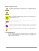
Warnings, Cautions, Notes, and Tips Refer all service to qualified personnel. This symbol warns of possible personal injury or equipment damage under noted conditions. Follow all safety standards of professional practice and the recommendations in this manual. Using this equipment in ways other than described in this manual can present serious safety hazards or cause equipment damage.
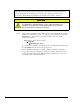
Your order was carefully inspected prior to shipment. When you receive your order, carefully unpack all items from the shipping carton and check for physical signs of damage that may have occurred during shipment. Promptly report any damage to the shipping agent and your sales representative. Retain all shipping materials in case the unit needs returned to the factory. CAUTION Using this equipment in ways other than described in this manual can cause personal injury or equipment damage.
Table of Contents 1 – Daq Systems 2 – DaqScan/2000 Series, Device Overviews Overview …… 2-1 Product Features …… 2-2 System Applications …… 2-3 3 – Block Diagrams 4 – Connectors, Indicators, Cables, & Pinouts DaqScan/2000 Series Hardware …… 4-1 Cables ……4-3 Pinouts ……4-5 5 – Software 6 – Configuring the System for Operation 7 – CE Compliance and Noise Considerations 8 – Taking Measurements Introduction …… 8-1 Scanning …… 8-1 Triggering …… 8-2 Synchronous I/O Operations …… 8-3 Asynchronous I/O Operations ……
This product requires one of the following Operating Systems: Windows NT Windows 2000 Windows XP
Daq Systems 1 Daq Systems, the Modular Concept …… 1-1 DaqBooks, DaqBoards, and Daq PC-Cards ….. 1-2 Using DBK Cards and Modules for Signal Conditioning …… 1-4 Daq Software …… 1-5 This chapter provides a brief overview of Daq devices. Users interested in jumping straight to DaqScan information should skip directly to chapter 2. Daq Systems, the Modular Concept Daq equipment and software form a modular, interrelated family of products that provide great flexibility in data acquisition system design.
DaqView and DASYLab can only be used with one DaqScan/2000 Series device at a time. LabView can be used with multiple Daq/2000 Series devices. For multiple device applications (via custom programming) refer to the Using Multiple Devices section of the Programmer’s Manual. During software installation from the data acquisition CD (p/n 1022-0601), a PDF version of the Programmer’s Manual is automatically loaded onto your hard drive as a part of product support. The default location is the Programs directory.
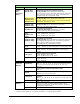
Daq Data Acquisition Devices Category Primary Data Acquisition Device DBK Option Cards and Modules* Software Device Description DaqLab/2001 DaqLab/2005 Ethernet-Based Laboratory Data Acquisition 16-bit, 200 kHz devices with Ethernet connectivity. Each can serve as host to an internal analog and/or digital DBK card. Each has a built-in AC-to-DC power circuit and can be plugged directly into a standard AC outlet.
Using DBK Cards and Modules for Signal Conditioning The DBK signal-conditioning cards and modules are designed for use with DaqLab, DaqScan, DaqBook, LogBook, and various data acquisition boards, i.e., ISA, PCI, and compact-PCI types. The DBKs perform best when used with an acquisition device that can dynamically select channel, gain, and range. DBK cards and modules with dynamic channel and gain/range selection allow for high channel-to-channel scan rates with a variety of transducers.
Daq Software The Daq devices have software options capable of handling most applications. Three types of software are available: • ready-to-use graphical programs, e.g.
1-6 Daq Systems 949595 DaqScan/2000 Series
DaqScan/2000 Series 2 Device Overviews Overview …… 2-1 Product Features …… 2-2 System Applications …… 2-3 Overview DaqScan/2000 Series devices are high-speed, multi-function, data acquisition devices for use with Ethernet PCs and Ethernet networks. Each unit connects directly to a PC’s Ethernet port or network hub. All I/O is accessed via female DB37 connectors located on the rear of the unit, making cabling easy from the DaqScan to the test device.
Each DaqScan/2000 Series model is packaged in 1U high (1.75”), 19” wide full-rack package, and includes a rackmount kit that can attach to either the front or the rear of the enclosure. Multiple DaqScan models can be combined in the same system. Up to 4 units can be synchronized [scan synchronous post-trigger] via rear panel SYNC connectors.
System Applications In addition to basic applications that make use of a DaqScan model’s built-in I/O, a wide variety of signal conditioning and expansion options make additional applications possible. Each of the following sample systems are obtained by using a DaqScan along with one or more DBK options.
2-4 Device Overviews 898095 DaqLab/2000 Series
Block Diagrams 3 DaqScan/2001 Block Diagram DaqScan/2000 Series 947495 Block Diagrams 3-1
DaqScan/2002 Block Diagram DaqScan/2004 Block Diagram 3-2 Block Diagram 947495 DaqScan/2000 Series
DaqScan/2005 Block Diagram DaqScan/2000 Series 947495 Block Diagrams 3-3
3-4 Block Diagram 947495 DaqScan/2000 Series
Connectors, Indicators, Cables, & Pinouts 4 DaqScan/2000 Series Hardware …… 4-1 Cables …… 4-3 Pinouts …… 4-5 DaqScan/2000 Series Hardware DaqScan Front Panel Front Panel The DaqScan/2000 Series front panels contain a power indicator LED. The power switch and connectors are on the rear panel.
POWER Switch and Power LED: A rocker-type switch with a “0” label for Power Off, and a “1” for Power On. When the unit is on and has power, the POWER LED will light. An AC to DC power converter resides within each DaqScan/2000 series device. MAC Address Label: The Media Access Control (MAC) label shows the device serial number in three formats: (1) Barcode, (2) base 10, and (3) hexadecimal. If prompted to enter a serial number in software, use the base 10 number.
Cables Should you need help in regard to cables or have any other product inquiries please contact the factory. Cables for use with DaqScan/2000 Series Devices Description Part No. 1. Molded expansion cable. Connects a DBK module to a DaqScan, 2 in. CA-255-2T 2. Molded expansion cable. Connects a DBK module to a DaqScan, 4 in. CA-255-4T 3. DBK expansion cable. Connects a DBK module to a DaqScan, 2.5 in. CA-37-1T 4. DBK expansion cable. Connects a DBK module to a DaqScan, 4.5 in. CA-37-3T 5.
4-4 Connectors, Indicators, Cables, & Pinouts 898095 DaqScan/2000 Series
Pinouts P1 – Analog I/O (Applies to DaqScan/2001 and DaqScan/2005 only) …… 4-6 P2 – Digital I/O …… 4-7 P3 – Pulse/Frequency/Digital I/O…… 4-8 CAUTION Turn off power to all devices connected to the system before connecting cables or setting configuration jumpers and switches. Electrical shock or damage to equipment can result even under low-voltage conditions. CAUTION The discharge of static electricity can damage some electronic components. Semiconductor devices are especially susceptible to ESD damage.
P1 (Applies only to DaqSCan/2001 and DaqScan/2004) P1 Pin 1 2 3 4 5 6 7 8 9 10 11 12 13 14 15 16 17 18 19 20 21 22 23 24 25 26 27 28 29 30 31 32 33 34 35 36 37 4-6 Signal Name +5 Volts -15 Volts Expansion 7 Expansion 9 Expansion 5 Expansion 6 DGND Negative Reference Positive Reference Not Connected CH 15 (SE), or CH 7 LO DIFF CH 14 (SE), or CH 6 LO DIFF CH 13 (SE), or CH 5 LO DIFF CH 12 (SE), or CH 4 LO DIFF CH 11 (SE), or CH 3 LO DIFF CH 10 (SE), or CH 2 LO DIFF CH 9 (SE), or CH 1 LO DIFF CH 8 (SE), or
P2 P2 Pin 1 2 3 4 5 6 7 8 9 10 11 12 13 14 15 16 17 18 19 20 21 22 23 24 25 26 27 28 29 30 31 32 33 34 35 36 37 Digital I/O Signal Name Not Connected Not Connected Port B - B7 Port B - B6 Port B - B5 Port B - B4 Port B - B3 Port B - B2 Port B - B1 Port B - B0 DGND Not Connected DGND Not Connected DGND Not Connected DGND + 5 Volt Supply DGND + 5 Volt Supply DGND Port C - C7 Port C - C6 Port C - C5 Port C - C4 Port C - C3 Port C - C2 Port C - C1 Port C - C0 Port A - A7 Port A - A6 Port A - A5 Port A - A4 P
P3 Pulse/Frequency/Digital I/O P3 Pin 1 2 3 4 5 6 7 8 9 10 11 12 13 14 15 16 17 18 19 20 21 22 23 24 25 26 27 28 29 30 31 32 33 34 35 36 37 4-8 Signal Name DGND DGND Digital 7 Digital 6 Digital 5 Digital 4 Digital 3 Digital 2 Digital 1 Digital 0 DGND Expansion 2 Expansion 3 Expansion 4 Timer 0 Timer 1 Counter 2 Counter 0 + 15 Volts + 5 Volt Supply Analog Out Clock Digital 15 Digital 14 Digital 13 Digital 12 Digital 11 Digital 10 Digital 9 Digital 8 AGND Analog Out DAC 3 Analog Out DAC 2 Analog Out DAC 1
Software 5 Overview …… 5-1 Out-of-the-BoxTM Software …… 5-1 Drivers for Third-party, Icon-driven Software …… 5-2 Language Drivers …… 5-2 Overview The Daq devices have software options capable of handling most applications. Three types of software are available: • Out-of the-box graphical programs, e.g., DaqView, DaqViewXL, and post acquisition data analysis programs such as eZ-PostView, eZ-TimeView, and eZ-FrequencyView. • drivers for third-party, icon-driven software such as DASYLab and LabVIEW.
Reference Notes: ¾ ¾ PDF Note: The software documentation for DaqView, DaqViewXL, and Post Acquisition Data Analysis are not included as part of the hardcopy manual, but are available in PDF format. See the PDF Note, below. Programming topics are covered in the Programmer’s User Manual (1008-0901). As a part of product support, that manual is automatically loaded onto your hard drive during software installation.
Configuring the System for Operation Step Step Step Step Step Step Step 1 2 3 4 5 6 7 - 6 Install the Software …..
STEP 1 – Install the Software 1. Remove previous version Daq drivers, if present. You can do this through Microsoft’s Add/Remove Programs feature. 2. Place the Data Acquisition CD into the CD-ROM drive. Wait for PC to auto-run the CD. This may take a few moments, depending on your PC. If the CD does not auto-run, use the Desktop’s Start/Run/Browse feature to locate and run Setup.exe [from the applicable CD-ROM drive]. 3. After the intro-screen appears, follow the screen prompts.
Dedicated Network - making use of a network hub or switch In the following figure a DaqLab/2000 Series device is connected to the Ethernet through a network hub/switch. At least one computer is also connected to the hub. DaqScan/2000 series devices can be connected directly to the hub/switch in the same manner. Dedicated Network using a Hub/Switch Some network devices such as a wireless access point may act as a DHCP server. If this is the case, follow the instructions for the LAN with a DHCP server.
Notes: ¾ Using a DaqLab/2000 Series or DaqScan/2000 Series device on a typical LAN may affect the speed of the network and internet data transfer. Because of this we recommend adding a network card to the computer and using one of the two dedicated network configurations. ¾ Contact your network administrator before connecting your device to a corporate network.
STEP 4 – Power-up the System What you will need: A 90 to 240 VAC power supply. Your unit’s power supply cord. How to make the connection: In the following steps we use the term “Daq Device” to mean a DaqLab/2000 Series device or DaqScan/2000 Series device as applicable to your system. 1. Using the unit’s power switch, turn the Daq device “OFF.” The switch will be in the “0” position and the power LED will be unlit. 2. Connect the power cord to the Power In connector on the Daq device. 3.
STEP 5 – Configure the Computer’s Network Settings [Applies to “dedicated networks” only] If using a LAN (Local Area Network), which has a DHCP server, skip this section and continue with STEP 7 - Configure and Test the System using the Daq*Configuration Applet (page 6-10). If using a LAN (Local Area Network), which has no DHCP server, skip this section and continue with STEP 6 - Configure Device Network Settings using DaqIPConfig (page 6-9). 1.
Local Area Connection Properties 5. Double-click the “Internet Protocol (TCP/IP)” component (previous figure). The “Internet Protocol (TCP/IP) Properties” box will appear (following figure).
Configure the Computer’s TCP/IP settings as follows. Make sure that each computer on the dedicated network has a unique IP address. Make sure that the IP address of the acquisition device is also unique. The computer and the device cannot use the same IP address. Internet Protocol (TCP/IP) Properties 6-8 6. Select the “Use the following IP Address” radio button. 7. Set the IP address field to 10.0.0.x where x is some number from 1 to 255.
STEP 6 – Configure Device Network Settings using DaqIPConfig Applies only to a LAN (Local Area Network), which has a no DHCP server. If using a LAN (Local Area Network), which has a DHCP server, skip this section and continue with STEP 7 - Configure and Test the System using the Daq*Configuration Applet (page 6-10). The DaqIPConfig applet, designed for 32-bit Windows NT/2000/XP systems, allows you to change the IP address of a device to match the address of a host computer.
STEP 7 – Configure and test the System using the Daq* Configuration Applet The Daq* Configuration applet, designed for 32-bit Windows NT/2000/XP systems, is located in the Windows Control Panel. It allows you to add or remove a device and change configuration settings. The included test utility provides feedback on the validity of current configuration settings, as well as performance summaries. 1. Open the Daq* Configuration Applet. a.
Users of Dedicated Networks follow these 2 steps. a. Enter the Serial Number of the first-level device, e.g., DaqLab/2001. In the following screen shots the Serial Number is 800069. b. Select the “Auto IP Setting” radio button. Note that the IP Address of the DaqLab/2001 will automatically be calculated and displayed in the IP Address field as indicated in the following left-hand figure. c. Click the button.
The Pinging Device test is an ICMP (Internet Control Message Protocol) ping test. In addition to indicating either “Passed” or “Failed,” the test displays the round-trip time of the ping, for example, <10 ms; and Packet Loss expressed as a percent of data lost. A long ping round trip time, for example, >50 ms and/or any packet loss indicates a slow network that is not optimized. If the Pinging Device Test fails a button will appear just above the button.
CE Compliance & Noise Considerations 7 Overview ……7-1 CE Standards and Directives …… 7-1 Safety Conditions ……7-2 Emissions/Immunity Conditions ……7-2 CE Enhancements for DBKs .…… 7-3 CE Compliance for System Expansion …… 7-3 Noise Considerations …… 7-4 Overview CE-compliant products bear the “CE” mark and include a Declaration of Conformity stating the particular specifications and conditions that apply.
For clarification, terms used in some Declarations of Conformity include: • pollution degree: any addition of foreign matter, solid, liquid or gaseous (ionized gases) that may produce a reduction of dielectric strength or surface resistivity.
CE Enhancements for DBKs The following CE enhancements are detailed in the DBK Cards and Modules User’s Manual (p/n 457-0905). • • • DBK41/CE Edge Guard (for DBK5, DBK8, and DBK44) Applicable cables and connectors CE Compliance for System Expansion The Daq devices are CE compliant at the time they leave the factory, and will remain in compliance providing that the conditions stated on their respective Declaration of Conformity cards continue to be met.
Noise Considerations Controlling electrical noise is imperative because it can present problems even with the best measurement equipment. Most laboratory and industrial environments suffer from multiple sources of electrical noise. For example, AC power lines, heavy equipment (particularly if turned on and off frequently), local radio stations, and electronic equipment can create noise in a multitude of frequency ranges.
Taking Measurements 8 Introduction …… 8-1 Scanning …… 8-1 Triggering …… 8-2 Synchronous I/O Operations…… 8-3 Asynchronous I/O Operations …… 8-5 Synchronizing Multiple Units …… 8-6 Using DBK Cards and Modules for Signal Conditioning ….. 8-8 Introduction With signal lines connected and a system up and running you can begin acquiring data. Specific connector details and pinouts are provided in chapter 4.
Triggering Triggering can be the most critical aspect of acquiring data. DaqScan/2000 Series devices support a full complement of trigger modes to accommodate a wide variety of applications. Hardware Analog Triggering. Many data acquisition products claim analog triggering, but rely on the PC to take readings and make a decision, which leads to uncertain and potentially long latencies.
Pre- and Post-Triggering Modes. Six modes of pre- and post-triggering are supported, providing a wide variety of options to accommodate any measurement requirement. When using pre-trigger, the user must use software-based triggering to initiate an acquisition. • No pre-trigger, post-trigger stop event. This, the simplest of modes, acquires data upon receipt of the trigger, and stops acquiring upon receipt of the stoptrigger event. • Fixed pre-trigger with post-trigger stop event.
Channel Sampling Interval In regard to analog input, DaqScan/2001 and DaqScan/2005 allow for programmable sampling intervals of 5 us, 10 us, or 1000 us on a per channel basis. This mode allows some DBK expansion channels [that change slowly for a higher degree of accuracy] to be sampled at a longer interval, and channels that change more rapidly to be sampled at a shorter interval. Each 5 µs, 10 µs, or 1000 µs interval reduces the maximum aggregate acquisition rate for the entire scan by that amount.
Synchronous Output Data Source (DaqScan/2001 and DaqScan/2004 only) DaqScan/2001 and DaqScan/2004 allow the data source for synchronized DAC output operations to be that of an internal memory-based buffer. The output data, for all channels, is contained in the buffer. Asynchronous I/O Operations Each DaqScan/2000 Series device allows asynchronous input of any counter or digital channel that is not currently configured for synchronous acquisition.
Synchronizing Multiple Units Up to four DaqScan/2000 Series devices can be synchronized to each other via their rear panel SYNC connectors and associated cables. Each device has two identical SYNC ports; either [or both] can be used to connect units. The DaqScan units can be scan-synchronized and triggered from any other SYNC-connected unit. Note that cables CA-74-1 and CA-74-5 are 1-foot and 5-foot in length, respectively. The total combined cable length of the Sync cables is not to exceed 15 feet (4.
In regard to synchronization, the following applies: • One of three signals can be used to drive the DaqScan/2000 Series acquisition scan rate. These are: − the internal acquisition pacer clock − an external acquisition pacer clock (for DaqScan/2001 and /2005 only) − the global sync (G-SYNC) input from the SYNC ports • Both the SYNC connector input and the external clock input can be divided down.
Using DBK Cards and Modules for Signal Conditioning The DBK signal-conditioning cards and module are designed for use with DaqLabs, DaqScans, DaqBooks, LogBooks, and various types of data acquisition boards, i.e., ISA, PCI, and compact-PCI types. The DBKs perform best when used with an acquisition device that can dynamically select channel, gain, and range. DBK cards and modules with dynamic channel and gain/range selection allow for high channel-to-channel scan rates with a variety of transducers.
Calibration 9 Overview …… 9-1 Using DaqCal.exe …… 9-1 Overview Daqscan/2000 Series devices are digitally calibrated at the factory. The digital method involves storing a correction factor on the circuit board for each range at the time of calibration. Whenever a particular range is selected, the appropriate calibration constant is automatically applied to a compensating DAC, thereby calibrating the specific range.
9-2 Calibration 948695 Daqscan/2000 Series
Troubleshooting and Customer Support 10 Electrostatic Discharge (ESD), Handling Notice…… 10-1 Product Care …… 10-1 ReadMe Files and the Install CD-ROM ……10-2 DaqCOM Issues …… 10-2 Driver Support……10-2 Ethernet Problems …… 10-3 Frequently Asked Questions …… 10-4 Customer Support …… 10-5 Electrostatic Discharge (ESD), Handling Notice The discharge of static electricity can damage some electronic components. Semiconductor devices are especially susceptible to ESD damage.
ReadMe Files and the Install CD-ROM The Install CD-ROM includes ReadMe Files. These files often contain late-breaking information that may not appear in the user documentation. During installation you should review the ReadMe files when prompted to by the program. The Install CD-ROM includes: • DaqBook/2000 Series1 Windows NT/2000/XP driver • DaqX.
Ethernet Problems • Make sure the Ethernet network is not experiencing technical problems. Check with your Network Administrator. • Ensure that your system is properly configured in the Daq Configuration Applet [located in the Windows’ Control Panel]. If a device is not configured correctly it will not be accessible from an application. • Verify that the correct MAC (Media Access Control) number is reflected by the software.
Frequently Asked Questions (1) Topic: Environmental Factors Question: What environments are the products intended for? Answer: Refer to the product specifications in regard to operating and storage temperature ranges, and relative humidity. Note that system components are not intended to be exposed to harsh environments and should always be protected from snow, rain, extreme dust, and harsh sun.
Customer Support If you want to Expand or Enhance Your Daq System . . . You can visit our internet site to find the latest accessories, expansion cards and modules. You can also contact us directly, see page ii for contact information. If you need to Report Problems or Request Product Support Note: Please do not return any equipment to the factory unless it has an RMA number (Return Merchandise Authorization number). RMA numbers are issued by the factory.
10-6 Troubleshooting & Customer Support 898095 DaqScan/2000 Series
Specifications 11 DaqScan/2000 Series General Supply Voltage Range: 90 to 250 VAC Power Required: 15W, assuming no DBK options Power Available for External Signal Conditioning & Expansion Options: 5V at 1A, ±15V at 500 mA, not to exceed 10W Operating Temperature: 0°C to + 50°C (32° to 122°F) Storage Temperature: -40°C to +80°C (-40° to 176°F) Relative Humidity: 0 to 95% non-condensing Vibration: MIL STD 810E, Categories 1 and 10 Signal I/O Connectors: DaqScan/2001 and DaqScan/2005: DB37 male connectors:
Specifications are subject to change without notice. Ranges: Software programmable via sequencer on a per-channel basis. Voltage Range (Note 1) Accuracy (Note 2) One Year, 0 to 35°C ±(% reading + % range) Input Noise (Note 3) (LSB rms) 10 Hz to 200 kHz Absolute 0.015 + 0.005 0.015 + 0.005 0.015 + 0.005 0.015 + 0.008 0.015 + 0.008 0.015 + 0.008 0.015 + 0.005 0.015 + 0.005 0.015 + 0.005 0.015 + 0.005 0.015 + 0.008 0.015 + 0.008 0.020 + 0.
Specifications are subject to change without notice. 2. Single-Channel Analog Software Trigger. Any analog input channel, including any of the analog expansion channels, can be selected as the software trigger channel. If the trigger channel involves a calculation, such as with temperature, then the driver automatically compensates for the delay required to calculate the reading, resulting in a maximum latency of one scan period.
Specifications are subject to change without notice. Digital I/O Channels: 40, expandable up to 272 with external digital DBK options Input Scanning Modes: 2 programmable 1. Asynchronous, under program control at any time relative to input scanning 2. Synchronous with input scanning Ports: 3 x 8-bit (82C55 emulation), and 1 x 16-bit; each port is programmable as input or output.
Specifications are subject to change without notice. Accessories and Cables Cables for use with DaqScan/2000 Series Devices Description Part No. 1. Molded expansion cable, 2 in. CA-255-2T 2. Molded expansion cable, 4 in. CA-255-4T 3. DBK expansion cable, not-molded, 2.5 in. CA-37-1T 4. DBK expansion cable, not-molded, 4.5 in. CA-37-3T 5. Expansion-card cable. Connects DBK series expansion card options. The “x” in the part no. indicates the number of cards that can be connected via the cable.
Specifications are subject to change without notice. This page is intentionally blank.
Glossary Acquisition A collection of scans acquired at a specified rate as controlled by the sequencer. Analog A signal of varying voltage or current that communicates data. Analog-to-Digital Converter (ADC) A circuit or device that converts analog values into digital values, such as binary bits, for use in digital computer processing. API Application Program Interface.
Differential mode voltage Differential mode voltage refers to a voltage difference between two signals that are referenced to a common point. Example: Signal 1 is +5 VDC referenced to common. Signal 2 is +6 VDC referenced to common. If the +5 VDC signal is used as the reference, the differential mode voltage is +1 VDC (+ 6 VDC - +5 VDC = +1 VDC). If the +6 VDC signal is used as the reference, the differential mode voltage is -1 VDC (+ 5 VDC - +6 VDC = -1 VDC).
WARRANTY/DISCLAIMER OMEGA ENGINEERING, INC. warrants this unit to be free of defects in materials and workmanship for a period of 13 months from date of purchase. OMEGA’s WARRANTY adds an additional one (1) month grace period to the normal one (1) year product warranty to cover handling and shipping time. This ensures that OMEGA’s customers receive maximum coverage on each product. If the unit malfunctions, it must be returned to the factory for evaluation.
Where Do I Find Everything I Need for Process Measurement and Control? OMEGA…Of Course! Shop online at omega.