
Products, Inc Computer Hardware User Manual


2.8 D/A Conversion
The OME-A-822PGL/PGH provides two 12 bit D/A converters. Before
using the D/A converter function, you should address the following items:
z D/A output register, BASE+4/BASE+5/BASE+6/BASE+7, (sec. 2.4.3)
z JP1 jumper set to internal reference voltage -5V or -10V (sec. 2.3.1)
z JP2 jumper set to internal or external reference voltage (sec. 2.3.2)
z If JP2 is set to internal and JP1 is set to -5V, the D/A output range is 0 to 5V
z If JP2 is set to internal and JP1 is set to -10V, the D/A output range is 0 to 10V
z If JP2 is set to external, the external reference voltage can be AC/DC +/- 10V
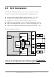
The block diagram is given below:
OME-A-822PGL/PGH
D/A channel 0
Base+4/+5
Ref
JP1
JP2
-5/-10 V
Internal
Reference
D/A channel 1
Base+6/+7
Ref
CN3
D0..D7
30
31
32
9,10,14,28,29
Analog
Gnd
V0+ V0-
Vref0+ Vref0-
V1+ V1-
Vref1+
12
Vref1-
NOTE : The D/A output latch registers use a “double buffer” structure. The user must
send the low byte data first, then send the high byte data. If the user
only sends the high byte, the low byte data will be the previous value.
OME-A-822PGL/PGH Hardware Manual ---- 31