
Owner's manual


8
2.4 Network Communication Interfaces
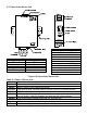
2.4.1 10Base-T RJ-45 Pinout
The 10BASE-T Ethernet network (RJ-45) system is used in the iServer for network
connectivity. The 10 Mbps twisted-pair Ethernet system operates over two pairs of wires.
One pair is used for receiving data signals and the other pair is used for transmitting data
signals. This means that four pins of the eight-pin connector are used.
Figure 2.6 RJ45 Pinout
2.4.2 10Base-T Crossover Wiring
When connecting the iServer directly to the computer, the transmit data pins of the
computer should be wired to the receive data pins of the iServer, and vice versa. The
10Base-T crossover cable with pin connection assignments are shown below.
Figure 2.7 10Base-T Crossover Cable Wiring
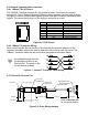
2.5 Probe with Pressure Port
Figure 2.8 Probe Wiring Hookup
0.75 [19.1] HEX
PTIH-10-6P
CONNECTOR
PT06F-10-6S
CONNECTOR
DB9 CONNECTOR or
STRIPPED LEADS
SHIELDED CABLE
1/8-27 NPT
0.38 [9.8]
0.82 [21.0] 1.21 [30.7]
1.83 [46.5]
20' [6.1m]
1.59 [40.4]
Pin Name Description
1 +Tx + Transmit Data
2 -Tx - Transmit Data
3 +RX + Receive Data
4 N/C Not Connected
5 N/C Not Connected
6 -Rx - Receive Data
7 N/C Not Connected
8 N/C Not Connected
Use straight through cable for
connecting the iServer to an
Ethernet hub. The ports on the
hub are already crossed
Refer to Section 2.3
for connector details.