
Owner's manual


7
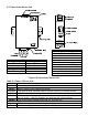
2.3 Parts of the iServer Unit
Figure 2.5 Parts of the iServer Unit
Table 2.1 Parts of iServer Unit
SENSOR DB9 or Screw Terminal Block Connections
ETHERNET RJ45 interface for 10BASE-T connection.
RESET Button: Used for power reseting the iServer.
ACTIVITY LED (Red) Blinking: Indicates network activities (receiving or sending packets).
NET LINK LED (Green) Solid: Indicates good network link.
DIAG LED (Yellow and Green) Diagnostics: at boot-up they light up for 2 seconds, then
turn off; DHCP: if DHCP is enabled, they blink and stay solid periodically
POWER LED (Green) Solid: Indicates Power-ON (for -W model only).
DC Power Supply Section:
+ Plus power supply wire connection (inside the plug for -W model).
- Minus power supply wire connection (outside the plug for -W model).
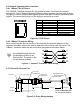
iPTX-D
Pin# Top
Connector
5 DATA IN GREEN / B
6 SCLK BLUE / F
7 N/A
8 N/A
Pin #
Bottom
Connector
1 +3.3V WHITE / A
2 RTN ORANGE / C
3 N/A
4 DATA OUT BLACK / D
Refer to Section 2.5 for Probe details
iPTX-W DB9
Pin# Signal Pin# Signal
1 DATA OUT 6 DATA IN
2 N/A 7 SCLK
3 N/A 8 N/A
4 N/A 9 +3.3V
5 RTN