MADE IN USA User’s Guide Shop on line at ® ® omega.com e-mail: info@omega.com For Latest Product Manuals omegamanual.
® ® OMEGAnet® On-Line Service www.omega.com Internet e-mail info@omega.com Servicing North America: USA:PP PP PP One Omega Drive, P.O. Box 4047 Stamford CT 06907-0047 TEL: (203) 359-1660PP FAX: (203) 359-7700 e-mail: info@omega.com Canada:: P PP PP PP 976 Bergar Laval (Quebec) H7L 5A1 TEL: (514) 856-6928PP e-mail: info@omega.
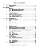
TABLE OF CONTENTS Part 1: Introduction 1.1 Safety and EMC Considerations .................................................................2 1.2 Before You Begin..........................................................................................2 1.3 Description....................................................................................................2 Part 2: Hardware 2.1 Mounting ......................................................................................................4 2.1.
Part 5: Specifications .......................................................................................................... 35 Part 6: Factory Preset Values ..............................................................................................36 Appendix A Glossary ......................................................................................................37 Appendix B IP Address ..................................................................................................
NOTES, WARNINGS and CAUTIONS Information that is especially important to note is identified by the following labels: • NOTE • WARNING or CAUTION • IMPORTANT • TIP NOTE: Provides you with information that is important to successfully setup and use the iServer. CAUTION or WARNING: Tells you about the risk of electrical shock. CAUTION, WARNING or IMPORTANT: Tells you of circumstances or practices that can effect the instrument’s functionality and must refer to accompanying documents.
PART 1 INTRODUCTION 1.1 Safety and EMC Considerations Refer to the CE Approval Section EMC Considerations • Whenever EMC is an issue, always use shielded cables. • Never run signal and power wires in the same conduit. • Use twisted-pair wires for signal connections. • Install Ferrite Bead(s) on signal wires close to the instrument if EMC problems persist. Failure to follow all instructions and warnings may result in injury! 1.
Typical Applications. The iServer is great for monitoring air (inert gas) pressure and temperature in applications such as: HVAC systems, pharmaceutical and food processing and storage, hospitals, laboratories, semiconductor fabs, electronic assembly, warehousing, museums, manufacturing, greenhouses, farm animal shelters, and many more. Email Alarms.
PART 2 HARDWARE 2.1 Mounting 2.1.1 Mounting the Wall Mount iServer Position unit where required. Mark and drill holes as required. If unit is to be mounted on a flat surface, you may take the bottom rubber feet off the unit. It is recommended that you ground your unit by wrapping a wire around the mounting tab screw and tightening a lock washer so that it embeds itself into the metal of the mounting tab. 3.55 [90.2] 3.05 [77.5] 2.42 [61.6] ETHERNET RESET ACTIVITY NETWORK LINK DIAGNOSTICS 0.25 [6.4] 0.
2.1.2 Mounting the DIN Rail iServer To install unit onto DIN Rail: a) Tilt unit, position mounting slot onto DIN Rail, as shown. b) Push unit towards DIN Rail and it will snap into place. Figure 2.2 Mounting - DIN Rail iServer 2.1.3 Removal from a DIN Rail a) Insert flat screw-driver into tab and push downwards. b) Unit will detach from DIN Rail. Figure 2.
2.2 DIP Switches 2.2.1 DIP Switch Usage The iServer is shipped with all DIP switches in "OFF" position. 1) 2) 3) 4) N/C - not used To change to default factory settings To enable/disable DHCP N/C - not used To set the iServer to factory default settings, slide DIP switch #2 to ON position. Power the iServer on and wait about 10 seconds until the iServer fully boots up.
2.3 Parts of the iServer Unit Pin# 1 2 3 4 5 Signal DATA OUT N/A N/A N/A RTN iPTX-W DB9 Pin# 6 7 8 9 iPTX-D Pin# Top Connector 5 DATA IN GREEN / B 6 SCLK BLUE / F 7 N/A 8 N/A Pin # Bottom Connector 1 +3.3V WHITE / A 2 RTN ORANGE / C 3 N/A 4 DATA OUT BLACK / D Refer to Section 2.5 for Probe details Signal DATA IN SCLK N/A +3.3V Figure 2.5 Parts of the iServer Unit Table 2.
2.4 Network Communication Interfaces 2.4.1 10Base-T RJ-45 Pinout The 10BASE-T Ethernet network (RJ-45) system is used in the iServer for network connectivity. The 10 Mbps twisted-pair Ethernet system operates over two pairs of wires. One pair is used for receiving data signals and the other pair is used for transmitting data signals. This means that four pins of the eight-pin connector are used.
PART 3 NETWORK CONFIGURATION 3.1 Network Protocols The iServer can be connected to the network using standard TCP/IP protocols. It also supports ARP, HTTP (WEB server), DHCP, DNS and Telnet protocols. 3.2 Ethernet (MAC) Address MAC (Media Access Control) address is your computer's unique hardware number. When you're connected to the LAN from your computer, a correspondence table relates your IP address to your computer's physical (MAC) address.
3.3 DHCP DHCP, Dynamic Host Configuration Protocol enables individual computers or devices to extract their IP configurations from a server (DHCP server). If the DHCP is enabled on your iServer, as soon as the iServer is connected to the network, there is an exchange of information between DHCP server and the iServer. During this process the IP address, the Gateway address, and the Subnet Mask will be assigned to the iServer by the DHCP server.
3.5.1 Default IP Address The iServer is shipped with a default IP address of 192.168.1.200 and Subnet Mask of 255.255.255.0. If you are going to use a Web browser or Telnet program to access the iServer using its default IP address, make sure that the PC from which you’re establishing the connection has an IP address that is in the same range as the iServer’s IP address (192.168.1.x, where x can be any number from 1 to 254. Your PC’s IP address cannot be the same as the iServer’s IP address.
PART 4 OPERATIONS This iServer can be used and configured in several ways, depending on user’s preference and network setup. It can be configured using a Web browser, like Netscape or Internet Explorer. It can also be configured using NEWPORT’s iCONNECT Configuration Software. If DHCP and DNS servers are used, the connection is very simple, no need to find the right IP address or watch for network conflicts, these are all done for you by your network DHCP and DNS server.
4.1 iCONNECT Software The iServer may also be assigned an IP Address by using the iCONNECT software. a) Download the iCONNECT software from the website listed in this manual. b) Install iCONNECT software on a networked PC. This software is compatible with Windows 95, 98, NT, 2000, and XP. c) Use iCONNECT to assign an IP address to the iServer and access its web pages for configuration. You can also use any standard web browser to access the iServer’s web pages.
4.2 Setting a New IP Address over the Network Besides using the iCONNECT software, you may use the iServer’s default IP address to access it and assign a new IP address to it. The iServer is shipped with a default IP address of 192.168.1.200 and Subnet Mask of 255.255.255.0. You can configure your PC’s Network connection with an IP address that is in the same range as the iServer’s IP address (192.168.1.x) and connect to the iServer using a crossover network cable between your PC and the iServer.
4.3 Setup and Operation Using a Web Browser • Start your web browser. • From the browser you type http://eisxxxx using the last four-digits from the MAC address label located on the device if DHCP and DNS are used. If a static IP address is used, then simply type http://x.x.x.x, where x.x.x.x is the iServer’s IP address. • The Home Page, shown in Figure 4.5, will be displayed. iServer Home Page http://192.168.1.200 iSERVER HOME PAGE Read Sensor Chart Access Control Configuration Firmware Version x.
4.3.1 Read Sensor • Click on Read Sensor . In a few seconds the following page (Figure 4.7) will appear with all default values of 100.00. Then the actual readings of Temperature and Air Pressure will be displayed. • This page automatically updates the Temperature and Air Pressure • Click on Main Menu to return to Home Page.
4.3.1.2 Java Runtime Environment 1.5 (5.0) Setup instructions 1. Go to your computer's Control Panel. Open the Java Plug-in 2. Click on "Settings" & "View Applets" in the "General" tab. 3. Select the "Settings" button on the General Tab Un-check the "Enable Caching" box. Then close dialog box to show the General Tab again 4. Select the "Network Settings" button on the General Tab. Proceed to the Browser tab. Follow the Browser Proxy Selection instructions below.
4.3.2 Chart • Click on Chart , the following page (Figure 4.8) should appear. The Java™ Applet graph displays Temperature and Air Pressure and can be charted across the full span (0 to 70ºC) or within any narrow range (such as 20-30ºC). Air (inert gas) pressure can be displayed in kilopascals (kPa), pounds per square inch (psi) or kilograms per square centimeter (Kg/cm2). The time-base can display one minute, one hour, one day, one week, or one month.
4.3.3 Configuration • Click on Configuration , the following page should appear. CONFIGURATION http://192.168.1.200 CONFIGURATION No. Sensor Name 1 2 Temperature Pressure Reading SRTC SRH# Display Units C PSI Remote Remote End Char Offset Format (HEX) T0000.0C P0000.0P 0D 0D 0000.0 0000.0 Click on Sensor No. on the left to modify Sensor Parameters.
4.3.3 Configuration (continued) B) Terminal Server TCP/UDP*: The iServer supports TCP and UDP protocols (default is TCP). If UDP is selected, it can be configured either for Broadcast UDP or Directed UDP. In case of Broadcast UDP, the iServer will transmit the data to every node on the network. This can be accomplished if the Remote IP Address is set to 255.255.255.255. The Broadcast UDP is a practical solution when one iServer needs to communicate with multiple nodes over the network.
4.3.4 Sensor Parameter • In the first column of Configuration’s page, click on 1 to view and modify Sensor Parameters. See Figure 4.9. Sensor Parameters http://192.168.1.200 SENSOR PARAMETERS Sensor No. 1 Temperature Sensor Name: SRTC Reading Command: Display Units: C T0000.0C Remote Display Format: Remote End Char (Hex)0x: 0D Offset: ( C or kPa) 0000.0 Update Reset Cancel Main Menu Figure 4.10 Sensor Parameters Below are some definitions of terms used in the Sensor Parameter page.
d. n 4.3.4 Sensor Parameters (continued) Remote Display Format: Is used for Terminal Server continuous mode. This determines the data format sent by the iServer to a remote network node (e.g. iLD Display) If no format is specified (blank), there is no reading sent out. If temperature is 75.7 and T00.0F is used in temperature setting, the remote site will show T75.7F. This format setup was originally made for the iLD Display, which has four or six LEDs. For six LEDs, T00.00F format, and for four LEDs, 00.
4.3.5 Access Control (continued) Access Control http://192.168.1.200 ACCESS CONTROL Login Password: 12345678 Admin Password: 00000000 Host Name: eis0e0f MAC Address: 0A:0B:0C:0D:0E:0F IP Address: 192.168.1.200 Gateway Address: Subnet Mask: 0.0.0.0 255.255.255.0 Save Reset Power Recycle Main Menu Figure 4.12 Access Control Login Password: This allows users to access and modify all of the iServer Home Page menu items, except “Access Control”, which requires an Administrator password.
4.3.5 Configure Access Control (continued) Gateway Address: A gateway is a network point that acts as an entrance to another network. A gateway is often associated with a router, which knows where to direct a given packet of data that arrives at the gateway. If the iServer is sending packets to another network node that is not on the same network on which the iServer is connected, a gateway address needs to be given to the iServer.
4.5.1 HTTPGET using Port 1000 You can setup and read the information from the iServer by using the HTTPGET program. The following program can be used to read data from the embedded server firmware by using TCP port 1000. The command string is sent to this TCP port, then the response can be read back from the same socket. The Httpget.exe file is used to setup and read information from the iServer.
4.5.2 HTTPGET and ARP to setup Device IP Address Use the iCONNECT software, which may be downloaded from our website, to do these IP changes whenever possible. Use ARP first to assign the mac address to a static IP address in computer arp table by this command: apr –s 192.168.1.200 00-03-34-00-00-06-b6 Then use the following command to assign new IP to the device: Httpget –r –S "00000000" 192.168.1.200:1 where: “0000000” is admin. password. If the password is wrong, the unit will ignore the new IP.
4.6 ARP Protocol (continued) The following window shows examples of arp commands and responses. • Your computer has an IP address of 192.168.1.118 • The destination computer has an IP address of 192.168.1.96 C:\>arp - 192.168.1.96 No ARP Entries Found C:\>ping 192.168.1.96 Pinging 192.168.1.96 with 32 bytes of data: Reply Reply Reply Reply from from from from 192.168.1.96=bytes=32 192.168.1.96=bytes=32 192.168.1.96=bytes=32 192.168.1.
4.7 Remote Access (Tunneling) To "tunnel", in this context, is to transmit data between two points through a private conduit on a shared or public network. The network could be an Ethernet LAN, a WAN, or the Internet. There is a Serial-to-Ethernet iServer that allows for a connection between a serial device and a PC, or between two serial devices, using an existing network rather than dedicated wiring.
4.7.1 Local iServer 1. An IP address should be assigned to the iServer dynamically or statically (recommended). 2. Use a browser to access the Local iServer’s WEB page. Simply type the iServer’s IP address at the browser’s URL location (i.e. 192.168.1.49) followed by an Enter key. You should then see the iServer’s main WEB page. 3. Click on the Update button. 4. Click on Configuration, you will be prompted with a Password (default is 12345678). 5.
4.7.2 Remote iServer 1. An IP address should be assigned to the iServer either statically or using a DHCP server. Refer to the DHCP section of the user’s manual for details. 2. Use a browser to access the Remote iServer’s WEB page. Simply type the iServer’s IP address at the browser’s URL location (i.e. 192.168.1.50) followed by an Enter key. You should then see the iServer’s main WEB page. 3. Click on the Update button. 4. Click on Configuration, you will be prompted with a Password (default is 12345678).
4.8 iLOG Software The iLOG software can be used only with NEWPORT Electronics instruments. This is an Excel application software that can log air pressure and temperature from an iServer over the Ethernet or the internet. a) b) c) Download the iLOG software from the website listed in this manual. Install iLOG software on a networked PC. This software is compatible with Windows 95, 98, NT, 2000, and XP. For complete information of how to use the iLOG software, click on the HELP button. Figure 4.
4.9 Mail Notifier Software The Mail Notifier Software can be used only with NEWPORT Electronics instruments. For complete information of how to use the Mail Notifier software, click on the Help menu of the main window. The Mail Notifier software generates email notifications for alarm conditions. Users can be notified automatically of alarm conditions monitored via internet connections throughout the world.
4.9.2 Program Options Setup and Configuration Complete program setup requires: • Entering a recipient for the email • Specifying connection details to MAPI services. • Defining alarms for devices, and selecting how and when the email will be active. Figure 4.20 iServer Mail Notifier Profile Setup The “Send To” tab contains a field to specify an email address to which alarm notifications will be sent (i.e. the recipient). Only one entry is permitted, in the address field.
4.9.3 Device Setting and Configuration Device setup requires: • Entering the IP address for iServer device (for example 192.168.1.200). • Specifying Socket number (1000 or 2000 depending on iServer settings). • Defining RS485 Unit # interface address (1 to 199). Enter "0" for RS232 interface or for iServer. • Entering Reading command. Normally set to SRT to obtain reading from the devices. If you want to change this setting, refer to HTTPget Section 4.5.
PART 5 SPECIFICATIONS SENSOR SPECIFICATIONS AIR (INERT GAS) PRESSURE (P) Accuracy/Range: 0 - 200 psi (0 - 14 bar ± 0.2) Resolution: 0.006 psi (0.4mbar) Maximum Safe Pressure: 250 psi absolute (17 bar abs) TEMPERATURE (T) Range*: 0°C to 70°C (32°F to 158°F) Accuracy*: ± 2°C (± 3.6°F) Response Time: 5 seconds Resolution: 0.01°C, 14 bit PROBE PHYSICAL DIMENSIONS Probe: 99.0 mm lg x 19.0 mm dia (3.9” x 0.
PART 6 FACTORY PRESET VALUES PRESET PARAMETERS Network Interface: IP Address Gateway Address Subnet Mask Device Host Name Login Password Admin Password DHCP Flow Control End Character Terminal Server: Server Type Number of Connections Port # TCP/UDP Remote Access (Tunneling): Remote Access Remote Port Remote IP Address FACTORY DEFAULTS 192.168.1.200 0.0.0.0 255.255.255.0 eis and last 4 digits from the MAC address 12345678 00000000 Disabled None 0D (Hex) (Carridge Return) Command 5 2000 TCP Disabled 2000 0.
APPENDIX A GLOSSARY User of this manual should be familiar with following definitions: ARP (Address Resolution Protocol) is a protocol for mapping an Internet Protocol address (IP address) to a physical machine address that is recognized in the local network. For example, the IP address in use today is an address that is 32-bits long. In an Ethernet local area network, however, addresses for attached devices are 48-bits long.
Appendix B IP Address An IP address is a unique 32-bit address assigned to a computer and includes: • A network ID number identifying a network. • A host ID number identifying a computer on the network. All IP addresses have been divided into three smaller groups (classes) A, B and C • Class A addresses have 8-bits of network ID and 24-bits of host ID. They can support a large number of hosts, approximately 2 = 16,777,216 computers per network. The IP addresses range in binary from 00000001.xxxxxxxx.
Appendix C IP Netmask IP Netmask or Subnet Mask is a 32-bit pattern of ones and zeros used to determine network portion of an IP address from the host portion of the IP address. Subnet mask is a network ID that is created by borrowing bits from host portion of IP address and using them as part of a network ID. The table below shows a default subnet mask for address Classes A, B, and C.
Appendix D ASCII Char NUL SOH STX ETX EOT ENQ ACK BEL BS HT LF VT FF CR SO SI DLE DC1 DC2 DC3 DC4 NAK SYN ETB CAN EM SUB ESC FS GS RS US SP ! " # $ % & ‘ ( ) * + , .
Appendix D / 47 0 48 1 49 2 50 3 51 4 52 5 53 6 54 7 55 8 56 9 57 : 58 ; 59 < 60 = 61 > 62 ? 63 2F 30 31 32 33 34 35 36 37 38 39 3A 3B 3C 3D 3E 3F ASCII Chart Continuation 00101111 o 111 p 00110000 112 q 00110001 113 00110010 r 114 00110011 s 115 00110100 t 116 00110101 u 117 00110110 v 118 00110111 w 119 00111000 x 120 y 00111001 121 00111010 z 122 { 00111011 123 | 00111100 124 } 00111101 125 00111110 ~ 126 00111111 DEL 127 6F 70 71 72 73 74 75 76 77 78 79 7A 7B 7C 7D 7E 7F 01101111 01110000 01110001 0
PART 7 APPROVALS INFORMATION 7.1 CE APPROVAL This product conforms to the EMC directive 89/336/EEC amended by 93/68/EEC, and with the European Low Voltage Directive 72/23/EEC. Electrical Safety EN61010-1:2001 Safety requirements for electrical equipment for measurement, control and laboratory.
WARRANTY/DISCLAIMER OMEGA ENGINEERING, INC. warrants this unit to be free of defects in materials and workmanship for a period of one (1) year from the date of purchase. In addition to OMEGA’s standard warranty period, OMEGA Engineering will extend the warranty period for one (1) additional year if the warranty card enclosed with each instrument is returned to OMEGA. If the unit malfunctions, it must be returned to the factory for evaluation.
Where Do I Find Everything I Need for Process Measurement and Control? OMEGA…Of Course! Shop on line at omega.