TM User’s Guide Shop online at omega.com e-mail: info@omega.com For latest product manuals: www.omegamanual.
omega.com info@omega.com U.S.A. Headquarters: Servicing North America: Omega Engineering, Inc. Toll-Free: 1-800-826-6342 (USA & Canada only) Customer Service: 1-800-622-2378 (USA & Canada only) Engineering Service: 1-800-872-9436 (USA & Canada only) Tel: (203) 359-1660 Fax: (203) 359-7700 e-mail: info@omega.com For Other Locations Visit omega.
PREFACE MANUAL OBJECTIVES This manual shows you how to set up and use the Programmable Process meter. NOTES, WARNINGS and CAUTIONS Information that is especially important to note is identified by three labels: • • • • NOTE WARNING CAUTION IMPORTANT NOTE: provides you with information that is important to successfully setup and use of the Process meter. CAUTION or WARNING: tells you about the risk of electric shock.
Table of Contents Section Page SEC 1 1.1 1.2 INTRODUCTION . . . . . . . . . . . . . . . . . . . . . . . . . . . . . 1 Unpacking . . . . . . . . . . . . . . . . . . . . . . . . . . . . . . . . . . . . 1 Safety Considerations . . . . . . . . . . . . . . . . . . . . . . . . . . . 2 SEC 2 2.1 2.2 2.3 ABOUT THE METER. . . . . . . . . . . . . . . . . . . . . . . . . . 3 Front of the Meter . . . . . . . . . . . . . . . . . . . . . . . . . . . . . . 3 Back of the Meter . . . . . . . . . . . . . . . . . . . . .
List of Figures Figures 2-1 2-2 2-3 3-1 3-2 3-3 3-4 3-5 3-6 3-7 3-8 3-9 3-10 A-1 A-2 C-1 Page Front-Panel . . . . . . . . . . . . . . . . . . . . . . . . . . . . . . . . . . . . . .3 Connectors (ac-Powered and dc-Powered) . . . . . . . . . . . . . . .5 dc-Power Connections . . . . . . . . . . . . . . . . . . . . . . . . . . . . . .6 S1 - S4 Jumpers . . . . . . . . . . . . . . . . . . . . . . . . . . . . . . . . . . .8 Meter - Exploded View . . . . . . . . . . . . . . . . . . . . . . . . . . . . .
NOTES iv
SECTION 1. INTRODUCTION 1.1 UNPACKING Remove the Packing List and verify that you have received all equipment. If there are any questions about the shipment, use the phone numbers listed on the back cover to contact the Customer Service Department nearest you. Upon receipt of shipment, inspect the container and equipment for any signs of damage. Note any evidence of rough handling in transit. Immediately report any damage to the shipping agent.
1.2 SAFETY CONSIDERATIONS This device is marked with the international caution symbol. It is important to read this manual before installing or commissioning this device as it contains important information relating to Safety and EMC (Electromagnetic Compatibility). This instrument is a panel mount device protected in accordance with EN 610101:2001, electrical safety requirements for electrical equipment for measurement, control and laboratory.
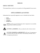
SECTION 2. ABOUT THE METER 2.1 FRONT OF THE METER Figure 2-1 shows each part of the front of the meter. Figure 2-1. Front Panel METER DISPLAY: Digital LED display: ¡.99 . 9 . . or 9.99 . 9 . . 4-digit 7–segment, 0.56" high LED display with programmable decimal point. METER MODES: Run Mode The meter is in the run mode when the display is actively showing a process. Configuration Mode The meter is in the configuration mode when you press the MENU button to enable meter configurations.
METER BUTTONS T-RST button - Clears the tare value. £/MAX button - In the run mode, press the £/MAX button to show the maximum value if jumper S3 is installed: the meter momentarily shows “####”, then flashes the maximum value encountered since the last peak reset. Press the £/MAX button to show the VALLEY value if jumper S3 is removed: the meter momentarily shows “™™™™”, then flashes the minimum value encountered since the last valley reset.
2.2 BACK OF THE METER Figure 2-2 shows the connectors on the back of the meter. Table 2-1 gives a brief description of each connector at the back of the meter. Refer to Figure 2-3 for dc-power connection information. Figure 2-2. Connectors for ac-Power (Top) and dc-Power (Bottom) Connector J1-1 J1-2 J1-3 J2-1 J2-2 J2-3 J3-1 J3-2 J3-3 J4-1 J4-2 J4-3 Table 2-1. Connector Description Description ac line connection (No Connection on dc-powered units). ac neutral connection (+ input on dc-powered units).
2.2 BACK OF THE METER (Continued) Figure 2-3. dc-Power Connections 2.3 DISASSEMBLY You may need to open up the meter for one of the following reasons: * * To check or change the 115 or 230 Vac power jumpers. To install or remove calibration jumper on the main board. Disconnect the power supply before proceedings. To remove and access the main board, follow these steps: 1. 2. 3. Disconnect the main power from the meter. Remove the front lens. Pull the meter forward, out of its case.
SECTION 3. GETTING STARTED CAUTION: The meter has no power-on switch, so it will be in operation as soon you apply power. If you power off/on the meter momentarily shows the following: “idP” for model type, “codE” , and “rxx” for the micro controller revision code. Keep track of revision code for future reference. 3.1 CHANGING CONFIGURATION JUMPERS The S1, S2 and S3 DIP switches are at the front of the meter near the digital display. The S4 DIP switch is on side of the main board (refer to Figure 3–3).
3.1 CHANGING CONFIGURATION JUMPERS (Continued) Front of the meter Figure 3-1. S1 - S4 Jumpers 3.2 MOUNTING THE METER PANEL CUTOUT Figure 3-2.
3.2 MOUNTING THE METER (Continued) PANEL THICKNESS 1. Cut a hole in your panel according to the dimensions specified in Figure 3-3. 6,4 (.25) MAX 0,8 (.03) MIN 1,5 R(.06) 4 PLCS 2. Insert the meter into the hole. Be sure the front bezel is flush to the panel. 45,00 + 0,61/-0,00 (1.772 + .024/–.000) 92,00 + 0,81/–0,00 (3.622 + .032/–.000) NOTE: Dimensions in Millimeters (Inches) Figure 3-3. Panel Cut-Out 3. Proceed to Section 3.4 to connect your sensor input. 3.
3.3 CONNECTING SENSOR INPUT (Continued) 1 2 3 J2 1 2 3 J3 1 2 3 0 10Vdc RTN I J4 V SIG SIG LOW HI SOURCE Figure 3-5. 2-Wire dc Voltage Input Connections with External Excitation 1 2 3 J2 1 2 3 J3 EXTERNAL SUPPLY 1 2 3 RTN I J4 V Figure 3-6.
3.3 CONNECTING SENSOR INPUT (Continued) 1 2 3 J2 1 2 3 HOLD 1 2 3 RTN EXC J3 EXC J4 I V Figure 3-7. 4-20 mA Transmitter Hook-Up with Internal Excitation 1 2 3 J2 1 2 3 J3 1 2 3 RTN I J4 V Figure 3-8.
3.4 CONNECTING MAIN POWER Connect the ac main power connections as shown in Figure 3-9. WARNING: Do not connect ac power to your meter until you have completed all input and output connections. Failure to do so may result in injury! J1 1 2 3 AC Power Line Neutral Earth Ground FUSE Figure 3-9. Main Power Connections - ac Table 3-2 shows the wire color and respective terminal connections for both USA and Europe. Table 3-2.
SECTION 4. CONFIGURING THE METER 4.1 SELECTING THE INPUT RANGE (INPT) Refer to Table B-2 for a summary list of menu configuration. To select your appropriate input range, follow these steps: 1. Press the MENU button. The meter flashes “InP”. 2. Press the ¢/TARE button. The meter flashes one of the following: * * * * * 0 - 10 (for 0-10 volt) 4 - 20 (for 4-20 mA) 20 - 4 (for 20-4 mA) 0 - 5 (for 0-5 volt) 1 - 5 (for 1-5 volt) 3. Press the ¢/TARE button to scroll through available choices. 4.
4.2 SELECTING A DECIMAL POINT POSITION (DEC.P) Refer to Table B-2 for a summary list of menu configuration. To select a decimal point display position, follow these steps: 1. Press the MENU button until the meter shows “dEc.P”. 2. Press the ¢/TARE button. The meter shows one of the following: * * * * * FFF.F FFFF. FFFF F.FFF FF.FF 3. Press the ¢/TARE button to move the decimal point to the right one position. 4. Press the MENU button to store your choice.
4.3.1 Internal Scaling Use internal scaling if you do not have an actual input signal to the meter. With internal scaling the input values are assumed to be the low and high signal input based on the selection input (e.g. if you selected 4-20 mA input, the “rd1” input value will be 0400 for 4 mA and “rd2” will be 2000 for 20 mA). All you need to do is change what the meter should read at these two points. For internal scaling, follow these steps: Refer to Table B-2 for a summary list of menu configuration.
4.3.2 Live Scaling Use live scaling when a stable input source is available (e.g. 4-20 mA or voltage calibrator). Also use live scaling when the actual input from your sensor can be set to output values close to the low and high ends of your input. For live scaling, follow these steps: Refer to Table B-2 for a summary list of menu configuration. 1. Press the MENU button until the meter flashes “ScAL” . 2. Press the ¢/TARE button until the meter shows “LivE”. 3. Press the £/MAX button.
4.4 CHANGING THE METER S CALIBRATION CAUTION: It is not necessary to calibrate a brand new meter, it arrives completely calibrated. The following procedure modifies the calibration of the meter. This procedure should only be performed by qualified personnel with accurate test equipment. To change the meter’s calibration, follow these steps: Disconnect the main power from the meter. 1. Install jumper S4 to enable the calibration procedure (refer to Figure 3-3). 2.
4.4 CHANGING THE METER S CALIBRATION (Continued) 10. Press the MENU button for the meter to accept the new value. The meter then flashes “rd2” . 11. Apply the high input voltage or current for the selected input range (e.g. apply 9.900 V if you are calibrating 0-10 V range). To calibrate the entire meter, you only need to calibrate the following three ranges: 0-10 V, 0-5 V and 4-20 mA. Table 4-1. Meter Calibration Table Range Low Input rd1* Input High 0-10V 0 Vdc 0000 9.9 Vdc 0-5, 1-5V 0 Vdc 0000 5.
APPENDIX A CHECKING AND CHANGING MAIN BOARD POWER JUMPERS IMPORTANT: If you want to change the Factory preset jumpers, do the following steps: Disconnect the power from the unit before proceeding. 1. Remove the main board from the case. Refer to Section 2.6. 2. Locate the jumpers W1, W2, W3 and W4 (located near the edge of the main board alongside the transformer). 3. If your power requirement is 115 Vac, install jumpers W1 and W2. If your power requirement is 230 Vac, install jumpers W4 and W3.
APPENDIX A CHECKING AND CHANGING MAIN BOARD POWER JUMPERS (Continued) JUMPER FOR 230Vac W4 W2 W3 W1 Figure A-2.
APPENDIX B REFERENCE TABLES MESSAGE 123* 123* ER 1 PrSt VrST T-RST Table B-1. Display Messages DESCRIPTION Peak value to follow Valley value to follow Peak value reached overload Valley value reached overload Scaling format error Peak reset Valley reset Tare reset. Clears tare value. * Represents any value Table B-2. Menu Configuration Displays MENU ¢/TARE £/MAX InP 0-10 4-20 20-4 0-5 1-5 DEC.P FFF.F FFFF. FFFF F.FFF FF.
APPENDIX B - REFERENCE TABLES (Continued) Table B-3. Run Mode Displays Display ¢/TARE £/MAX RESET T-RST Jumpers PrST Peak Reset Press to activate S3 installed VrST Valley Reset Press to activate S3 removed Peak Value to follow Valley value to follow Press to activate* S3 installed Press to activate* S3 removed T-RST Clears tare value Tare Display Press to activate Press to activate * Press ¢/MAX again to remove peak or valley reading and display process value. Table B-4.
APPENDIX C SPECIFICATIONS Analog Input Ranges: Input Impedance: Isolation: Accuracy: Tempco: Excitation Voltage: Display: 4-20 mA, 0-5 Vdc, 1-5 Vdc, 0-10 Vdc Voltage: 1.0 Meg Current: 100 Ω Dielectric strength to 2500V transient per 3mm spacing base on EN61010 for 260Vrms or dc working voltage 0.05%R +/- LSB +/- 50 PPM/°C 24 Vdc @ 25mA 10 Vdc @ 25mA LED 7-segment, 14.2 mm (0.
APPENDIX C - SPECIFICATIONS (Continued) 48.00(1.890) 96.00 (3.780) 0.73 (18.67) 3.22 (81.7) 3.74 (95.0) MAX SIDE VIEW TOP VIEW PANEL THICKNESS: 6,4 (.25) MAX 0,8 (.03) MIN 1,5 R (.06) 45,01 +0,61/-0,00 (1.772 +.024/-.000) 4 PLCS 92,00 +0,81/-0,00 (3.622 +.032/-.000) PANEL CUTOUT Figure C-1.
APPENDIX D - INFORMATION This product conforms to the EMC directive 89/336/EEC amended by 93/68/EEC, and with the European Low Voltage Directive 72/23/EEC. Electrical Safety EN61010-1:2001 Safety requirements for electrical equipment for measurement, control and laboratory. • Double Insulation: Primary to Secondaries • Pollution Degree 2 • Measurement *Category I Note 1: *Measurements performed on circuits not directly connected to the Mains Supply (power). Maximum Line-to-Neutral working voltage 50Vac/dc.
INDEX Calibration and the S4 jumper 7 changing 17, 18 installing/removing calibration jumper 6 Configuration jumpers changing 7, 8 Configuration mode 3 escaping from 4 RESET button 4 ßMAX button 4 ∂TARE button 4 Connecting sensor input 9-11 Connector label 5 dc-power 6 2-wire voltage input connections 10 3-wire voltage input connection 9 connectors 5, 6 current input connections 11 Decimal point disregarding in meter calibration 18 factory default 20 selecting 14 Disassembly 6 Front-panel buttons MENU 4 RES
INDEX Live scaling 16 Main board power jumpers 23, 24 MENU button 4 Meter modes configuration mode 3 run mode 3 micro controller revision code accessing 7 Mounting the meter 9 RESET button 4 Resetting peak and valley registers 4, 20 Run mode 3 MENU button 4 RESET button 4 ßMAX button 4 ∂TARE button 4 S1, S2 & S3 DIP switches changing 7 Scaling error message 19 internal 14, 15 live 14, 16 Scaling without known loads 14, 15 Sensor excitation factory default 20 Sensor input 9-11 connecting 9-11 T-RST button 4
WARRANTY/DISCLAIMER OMEGA ENGINEERING, INC. warrants this unit to be free of defects in materials and workmanship for a period of 13 months from date of purchase. OMEGA’s WARRANTY adds an additional one (1) month grace period to the normal one (1) year product warranty to cover handling and shipping time. This ensures that OMEGA’s customers receive maximum coverage on each product. If the unit malfunctions, it must be returned to the factory for evaluation.
Where Do I Find Everything I Need for Process Measurement and Control? OMEGA…Of Course! Shop online at omega.