
Owner's manual

7
MAINTENANCE
Chapter 4
MAINTENANCE
4.1 Verification of Performance
4.1.1 Calibration Interval
The DB Series instruments should be verified for
performance at a calibration interval of twelve (12)
months. This procedure may be carried out by the
user if a calibration capability is available, by Omega,
or by a certified calibration laboratory.
If the user should choose to perform this procedure,
then the considerations below should be observed.
4.1.2 General Considerations
It is important, whenever testing the DBX Series
Decade Units, to be very aware of the capabilities
and limitations of the test instruments used. A resis-
tance bridge may be employed, and there are di-
rect-reading resistance meters or digital multimeters
available that can verify the accuracy of these units,
especially when used in conjunction with standards
that can serve to confirm or improve the accuracy
of the testing instrument
Such test instruments must be significantly more ac-
curate than ±(l00ppm+2 mΩ) for all applicable
ranges, allowing for a band of uncertainty of the in-
strument itself. A number of commercial bridges and
meters exist that can perform this task; consult
Omega.
It is important to allow both the testing instrument
and the DBX Substituter to stabilize for a number
of hours at the nominal operating temperature of
23
O
C, and at nominal laboratory conditions of hu-
midity. There should be no temperature gradients
across the unit under test.
Substantial Kelvin type 4-wire test terminals should
be used to obtain accurate low-resistance readings.
It is convenient, once the zero resistance has been
determined, to subtract it from the remaining mea-
surements. This can be automatically done in many
instruments which have an offset subtraction capa-
bility.
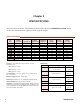
4.1.3 Procedure
1. Confirm the zero resistance of the unit.
2. Determine the allowable upper and lower
limits for each resistance setting of each decade
following the specified accuracy. For the
DBX series, these limits for any resistance
“R” are [R±(0.0001 R + 2 mΩ)]. For the A,
B, or Q series, see specifications.
3. Confirm that the resistances fall within these
limits after subtraction of the zero resistance.
4. If any resistances fall outside these limits, the
associated switch assembly may require
replacement.
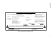
4.2 Schematic
Refer to Figure 4.1 for a schematic of the DB de-
cade unit.