User’s Guide Shop on line at ® omega.com e-mail: info@omega.com For Latest Product Manuals omegamanual.
It is the policy of OMEGA to comply with all worldwide safety and EMC/EMI regulations that apply. OMEGA is constantly pursuing certification of its products to the European New Approach Directives. OMEGA will add the CE mark to every appropriate device upon certification. The information contained in this document is believed to be correct, but OMEGA Engineering, Inc. accepts no liability for any errors it contains, and reserves the right to alter specifications without notice.
TABLE OF CONTENTS Part 1: Introduction 1.1 Safety and EMC Considerations .................................................................2 1.2 Before You Begin .........................................................................................2 1.3 Description....................................................................................................2 Part 2: Hardware 2.1 Parts of the End Device ..............................................................................5 2.
TABLE OF CONTENTS 4.6 4.7 4.8 (continued) ARP Protocol ..............................................................................................40 iLog Software..............................................................................................42 Mail Notifier Software.................................................................................43 4.8.1 Installation.....................................................................................43 4.8.
Figure 1.1 Figure 2.1 Figure 2.2 Figure 2.3 Figure 2.4 Figure 2.5 Figure 2.6 Figure 2.7 Figure 2.8 Figure 2.9 Figure 2.10 Figure 2.11 Figure 3.1 Figure 3.2 Figure 3.3 Figure 4.1 Figure 4.2 Figure 4.3 Figure 4.4 Figure 4.5 Figure 4.6 Figure 4.7 Figure 4.8 Figure 4.9 Figure 4.10 Figure 4.11 Figure 4.12 Figure 4.13 Figure 4.14 Figure 4.15 Figure 4.16 Figure 4.17 Figure 4.18 Figure 4.19 Figure 4.20 Figure 4.21 Figure 4.22 Figure 4.23 Figure 4.24 Figure 4.25 Figure 4.26 Figure 5.1 Figure 5.2 Figure 5.
iv
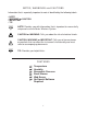
NOTES, WARNINGS and CAUTIONS Information that is especially important to note is identified by the following labels: • NOTE • WARNING or CAUTION • IMPORTANT • TIP NOTE: Provides you with information that is important to successfully setup and use the zSeries Wireless System. CAUTION or WARNING: Tells you about the risk of electrical shock. CAUTION, WARNING or IMPORTANT: Tells you of circumstances or practices that can effect the instrument’s functionality and must refer to accompanying documents.
PART 1 INTRODUCTION 1.1 Safety and EMC Considerations Refer to the Environment/Operating Conditions Section EMC Considerations • Whenever EMC is an issue, always use shielded cables. • Never run signal and power wires in the same conduit. • Use twisted-pair wires for signal connections. • Install Ferrite Bead(s) on signal wires close to the instrument if EMC problems persist. Failure to follow all instructions and warnings may result in injury! 1.
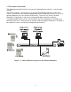
1.3 Description (continued) For example, you can select one End Device that has one internal and one external sensor to monitor temperature and humidity both inside and outside a climate-controlled facility. Each zSeries Coordinator can directly support up to thirty-two (32) End Devices. The Coordinators include AC adapters to operate on any voltage worldwide from 100-240 Vac and 50-60Hz. The Coordinator connects directly to an Ethernet Network or the Internet.
1.3 Description (continued) The following example illustrates how you can hookup zSeries wireless system to your network: The zSeries wireless system consists of a single Coordinator and one or more End Devices. End devices will send data periodically to the Coordinator where it serves as a gateway between the users and the End Devices. The users can access the data through the Coordinator’s web server and provided data acquisition software.
PART 2 HARDWARE 2.1 Parts of the End Device 11 2 3 1 4 Unit Addr Group Net. Addr 5 MODEL # SERIAL # 10 #.# 9 6 REAR 1 2 3 4 5 6 7 8 9 10 11 8 7 FRONT 8 position DIP switch (under cover), sets the NID and DID of the End Device (see Section 2.7 for details) Optional rear entry for external probes Label for Unit Address, Group No.
2.2 Dimensions and Mounting - End Device Position unit where required. Mark and drill holes as required, using a #6 screw. 1.81 [45.9] Material: PBT (Valox) Plastic Optional External Sensor 0.94 [23.8] 2.54 [64.5] 3.61 [91.8] REF 3.61 [91.8] 0.140 [3.56] 2 PLCS 1.90 [48.3] 0.32 [8.1] 2.54 [64.5] REF SIDE AND FRONT VIEWS INSIDE CASE, MOUNTING Figure 2.2 Mounting the End Device 2.
2.4 Disassembly - End Device You may need to open the unit for one of the following reasons: • To turn on Power Switch. • To mount unit to wall. Refer to Figure 2.2 for mounting dimensions. • To connect or replace the batteries, (note the polarity of batteries). • To access JTAG connector. Remove Cover as shown below, by pressing sides of cover to release latches. LATCH COVER LATCH DIP SWITCH SENSOR BOARD 8 1 EXTERNAL SENSOR/ PROBE MOUNTING SCREW TRAY BATTERY CLIPS JTAG POWER SWITCH Figure 2.
2.5 Parts of the Coordinator 1 2 3 4 5 6 7 8 9 10 11 12 13 14 15 16 Figure 2.5 Parts of the Coordinator Wall mounting bracket clip holes (3 places) Label with model and serial numbers Coordinator’s firmware revision on label 8 position DIP switch, from which the last 3 positions are used to assign the NID, network ID number (see Section 2.7 for details) Ethernet: RJ45 interface for 10BASE-T connection.
2.5 Parts of the Coordinator (continued) 17 Diagnostics LED: (Yellow and Green) Diagnostics: at boot-up they light up for 2 seconds, then turn off; DHCP: if DHCP is enabled, they blink and stay solid periodically Network Link LED: (Green) Solid: Indicates good network link. Activity LED: (Red) Blinking: Indicates network activities (receiving or sending packets). 18 Receive LED (blue) while blinking, the Coordinator looks for the clearest channel to communicate.
2.7 DIP Switches 2.7.1 DIP Switch Setup: Device ID (DID) The End Device is shipped with all DIP switches in the "OFF" position. For each End Device you can setup the unique Device ID using DIP switch #1 - 5. The Device ID also determines the Group of the End Device. The Coordinator puts every eight End Devices into a Group so that the system is more manageable. ON OFF You can setup the Network ID (NID) (which is the same as the Coordinator’s) with DIP switches # 6 - 8. Refer to Section 2.7.2.
2.7.2 DIP Switch Setup: Network ID (NID) Each sensor network has a unique Network ID (or NID). For the End Device and the Coordinator setup the Network ID with DIP switches #6 - 8 ON OFF If there is no other IEEE 802.15.4 system, the default NID can be used where all three dip switches are OFF.
2.7.3 DIP Switch Setup: Ethernet - Coordinator 4 1) 2) 3) 4) 1 OFF OFF ON 1 ON (Shown in "OFF" Position) 1 SERIAL 2 DEFAULT 3 DHCP 4 TERMINAL 8 N/C To change to default factory settings To enable/disable DHCP N/C Coordinator Figure 2.9 Ethernet - 4 Position DIP Switch Setup To set the Coordinator to factory default settings: 1) Slide DIP switch #2 to ON position. 2) Power the Coordinator on and wait about 10 seconds until the Coordinator fully boots up.
2.8 Network Communication Interfaces 2.8.1 10Base-T RJ-45 Pinout The 10BASE-T Ethernet network (RJ-45) system is used in the Coordinator for network connectivity. The 10 Mbps twisted-pair Ethernet system operates over two pairs of wires. One pair is used for receiving data signals and the other pair is used for transmitting data signals. This means that four pins of the eight-pin connector are used.
PART 3 NETWORK CONFIGURATION 3.1 Ethernet (MAC) Address MAC (Media Access Control) address is your computer's unique hardware number. When you're connected to the LAN from your computer, a correspondence table relates your IP address to your computer's physical (MAC) address.
3.4 DNS DNS, Domain Name System enables individual computers and devices to be recognized over a network based on a specific name instead of an IP address. For example, instead of having to use http://192.168.1.200 (IP address), you would use only http://z03ec or any sixteen character name stored as Host Name under Access Control menu in the zSeries Home Page. The default DNS name for the Coordinator is "z" followed by the last four digits of the MAC address of that particular Coordinator. 1.
3.5.2 Changing TCP/IP Properties on Your Computer Go to your computer’s Control Panel then Network Connections. Pick the network with the proper Ethernet card. Right click and choose Properties Look for Internet Protocol, click on it and press Properties Figure 3.2 Network Connections Setup the IP address (in this case, 192.168.1.1) as shown below and press OK You can access the Coordinator’s web server via any internet browser using IP address of 192.168.1.200.
PART 4 OPERATIONS This Coordinator can be used and configured in several ways, depending on user’s preference and network setup. It can be configured using a Web browser, like Netscape or Internet Explorer. It can also be configured using the iConnect Configuration Software. If DHCP and DNS servers are configured to exchange information, the connection will be very simple. All you need to do is to enable DHCP on the Coordinator (see Section 3.
4.1 iConnect Software The Coordinator may also be assigned an IP Address by using the iConnect software. a) Download the iConnect software from the website listed in this manual. b) Install iConnect software on a networked PC. This software is compatible with Windows 95, 98, NT, 2000, and XP. c) Use iConnect to assign an IP address to the Coordinator and access its web pages for configuration. You can also use any standard web browser to access the zSeries system’s web pages.
4.1 iConnect Software (continued) d) To access the zSeries system for Configuration: Click on the “View Webpage” button, you will access the zSeries home page, refer to Section 4.3 for details. Figure 4.
4.2 Setting a New IP Address over the Network Besides using the iConnect software, you may use the Coordinator’s default IP address to access it and assign a new IP address to it. The Coordinator is shipped with a default IP address of 192.168.1.200 and Subnet Mask of 255.255.255.0. You can configure your PC’s Network connection with an IP address that is in the same range as the Coordinator’s IP address (192.168.1.
4.3 Coordinator’s Configurations and Operations The Blue LED should blink for ~8 seconds and then stay on. It indicates that the Coordinator is searching for the least noisy channel and starts listening there. That’s when the blue LED changes from blinking to solid. Using a web browser, you should be able to view the homepage. • Start your web browser. • From the browser you type http://zxxxx using the last four-digits from the MAC address label located on the device if DHCP and DNS are used.
4.3.1 Power Up Device To verify that an End Device is working before deploying remotely, install batteries and power it on right next to the Coordinator. When the End Device is powered on, it will search for the Coordinator in all 16 channels reserved for IEEE 802.15.4 (channel 11 through 26) by sending request packets. While it’s searching, the blue LED on the End Device blinks every second.
4.3.2 Get Readings from the End Device Once you see the End Device’s LED blinking periodically, it means it is sending data which will appear on the “Readings” page. To view the data in a chart format, you can use the “Chart” page. Click on Readings from the Home Page, the following page will appear. Select the proper Group to view the readings. READINGS Address http://192.168.1.
4.3.2 Get Readings from the End Device (continued) While accessing the “Readings” page, If a blank screen appears without any “java application running” or image of a “Java logo”, please verify you have the latest Java Runtime Environment installed and configured according to the Section 4.3.3.1. If you do not have Java Runtime Environment, you may download it from our website or contact the Customer Service Department nearest you. The”Readings” fields are defined as follows: Name: Sensor name.
4.3.3 Java Runtime Environment Setup If your computer does not have Java installed, please download from java.sun.com. You can change the Java setting by clicking its icon in Control Panel. To load the applet, you have to enable the web browser and disable cache. 4.3.3.1 Java Runtime Environment 1.4 Setup instructions 1. Go to your computer's Control Panel. Open the Java Plug-in 2. Select the "Cache" Tab Un-check the "Enable Caching" box 3. Select the "Proxy" Tab.
4.3.3.2 Java Runtime Environment 1.5 (5.0) Setup instructions 1. Go to your computer's Control Panel. Open the Java Plug-in 2. Click on "Settings" & "View Applets" in the "General" tab. 3. Select the "Settings" button on the General Tab Un-check the "Enable Caching" box. Then close dialog box to show the General Tab again 4. Select the "Network Settings" button on the General Tab. Proceed to the Browser tab. Follow the Browser Proxy Selection instructions below.
4.3.3.3 Browser Proxy Selection Accessing Coordinators within your internal network • Usually when the computer and Coordinators are on an internal network, you will not use Proxy server access. • You should un-check the "Use Browser Settings" option on the "Proxy" tab. Accessing Coordinators units using the internet • Often the web browser will use Proxy server access to the internet. In such cases, the default Java runtime settings on the "Proxy" tab should suffice.
4.3.4 Java Policy To activate data logging and save graphs from the Java applets, it is necessary to create a Java Policy file and copy it onto a folder. 1) Open a Notepad file and using the IP address of the Coordinator type the following: grant codeBase “http://192.168.1.200/*” { Permission java.security.AllPermission “*”, “*”; }; This file should have the IP address of the Coordinator; in this case the default IP address is 192.168.1.200.
4.3.4 Java Policy (continued) 5) Change Java Applet’s Runtime Parameters found on the following path: a. Control Panel --> Java --> Java Control Panel --> Java Tab --> View b. Inside the box under the Java Runtime Parameters type the following: “-Djava.security.policy=C:\0_JAVAPOLICY\java_policy.txt” c. Click OK on the Java Runtime Settings window. d. Click Apply on the Java Control Panel window and then OK. 6) Close all opened Web browser.
4.3.5 Chart CHART Click on Chart , from the Home Page, the following page will appear. Select the proper Group to view the Chart. Address http://192.168.1.200 CHART: BY GROUP In a few seconds the following page will appear. The Java™ Applet graph displays Temperature, Humidity, and Barometric Pressure. It can be charted across the full span (-40 to 124ºC, and 0-100% RH) or within any narrow range (such as 20 to 30ºC).
4.3.5 Chart (continued) Save Current Graph: Save the current graph in PNG (Portable Network Graphics) format. The filename has extension .png. Max/Min Temperature: Maximum and minimum temperature of the current graph. If a sensor is selected (trend line and sensor name turns bold), its most current temperature reading is shown here. Temperature Unit Drop-down List: Temperature unit to be used, either ºC or ºF Max/Min Humidity: Maximum and minimum humidity of the current graph.
4.3.6 Diagnostic Click on Diagnostic , the following page will appear. Lab 50 Success 100% Strength 84% Update 10s Battery 3.06V Lab 100 Success 100% Strength 79% Update 10s Battery 3.21V NODE-3 Success 10% Strength 9% Update 10s Battery 3.08V NODE-4 Success 100% Strength 77% Update 10s Battery 3.14V NODE-5 Success 100% Strength 89% Update 10s Battery 2.34V Figure 4.15 Diagnostic Date and Time: Most recent time when data is received. Save Current Graph: Save the current graph in PNG format.
4.3.7 Configuration Click on Configuration from the Home Page, the following page will appear. CONFIGURATION Address http://192.168.1.200 CONFIGURATION Name zSeries Temperature C Pressure mbar TCP Connections 1 Port 02000 Save Reset Version x.x PID 13111 Channel 11 Transmit Power Range 20dBm Set Radio Please refer to local regulation for maximum transmit power range Reset Network Main Menu Figure 4.
4.3.7 Configuration (continued) Channel: Choose the operation channel defined in IEEE 802.15.4 for the sensor network. This allows you to select a wireless channel to communicate with the End Devices. It is strongly suggested to let the Coordinator to search for the best channel automatically, and by not touching this field. Transmit Power Range: This determines the signal power transmitted by the Receiver. The options are 10dBm and 20dBm.
4.3.8 Sensor Setup (continued) SETUPhttp://192.168.1.200 SENSOR SETUP # Check Sensor Name Update Seconds Units Power Firmware 0 ABCDEFGH 10 - - 1 ABCDEFGH 10 2 LAB 100 10 - - 3 ABCDEFGH 10 - - 0 4 ABCDEFGH 10 - - 0 5 ABCDEFGH 10 - - 0 6 ABCDEFGH 10 - - 0 7 ABCDEFGH 10 - - 0 C,mbar Battery 0 0 2.0 Click on Sensor # to modify Sensor Parameters Update Checked Box Take Readings View Charts Select Another Group Main Menu Figure 4.
4.3.8 Sensor Setup (continued) SENSOR PARAMETERS Address http://192.168.1.200 SENSOR PARAMETERS Sensor #3, Group A Sensor Name ABCDEFGI Update 10 (seconds) Offset1 (xxxx.x) 0 (C) Offset2 (xxxx.x) 0 (% or mbar) Offset3 (xxxx.x) (C) 0 Offset4 (xxxx.x) 0 Update Update rate is closely related to the lifetime of the battery. Since the End Device is in low power consumption (sleep mode) when idle, a longer update rate will cause less energy usage and prolong the life of the battery.
4.3.9 Access Control This section describes the "Access Control" page of the Web interface. This page allows the users to set up the network and security parameters of the zSeries wireless system. At the initial entrance to the “Access Control” page you may be prompted for the LOGIN Password (see Figure 4.6) prior to an ADMINISTRATOR Password. ACCESS CONTROL Address http://192.168.1.
4.3.9 Access Control (continued) IP Address: The IP (Internet Protocol) address is a 32-bit number that identifies each sender or receiver of information that is sent in packets across the Ethernet or the Internet. The Coordinator’s default IP address is 192.168.1.200. The Coordinator’s IP address should be changed to fit user’s networking environment. Consult with your IT department for obtaining an IP address. The DHCP will be enabled in the Coordinator if its IP address is set to 0.0.0.0.
4.5 HTTPget Program (continued) Whenever Terminal Server service (using Port 2000 by default) is required, the # of connections must be set to a value from 1 to 5. The Terminal Server mode is the recommended mode for the most reliable connection when operating with NEWPORT software or with other programs supporting TCP/IP communications.
4.5.2 HTTPget and ARP to Setup Device IP Address Use the iConnect software, which may be downloaded from our website, to do these IP changes whenever possible. Use ARP first to assign the mac address to a static IP address in computer arp table by this command: arp –s 192.168.1.200 00-03-34-00-00-06-b6 Then use the following command to assign new IP to the device: Httpget –r –S "00000000" 192.168.1.200:1 where: “0000000” is admin. password. If the password is wrong, the unit will ignore the new IP.
4.6 ARP Protocol (continued) The following window shows examples of arp commands and responses. • Your computer has an IP address of 192.168.1.118 • The destination computer has an IP address of 192.168.1.96 C:\>ping 192.168.1.96 Pinging 192.168.1.96 with 32 bytes of data: Reply Reply Reply Reply from from from from 192.168.1.96=bytes=32 192.168.1.96=bytes=32 192.168.1.96=bytes=32 192.168.1.96=bytes=32 time=5ms time=3ms time=3ms time=4ms C:\>arp -a 192.168.1.96 Interface: 192.168.1.
4.7 iLog Software This is an Excel application software that can log temperature, humidity and barometric pressure from the Coordinator over the local network (Ethernet) or the internet. a) Download the iLog software from the website listed in this manual. b) Install iLog software on a networked PC. This software is compatible with Windows 95, 98, NT, 2000, and XP. c) For complete information of how to use the iLog software, click on the HELP button. d) There is a list of Error Messages in Appendix E.
4.8 Mail Notifier Software For complete information of how to use the Mail Notifier software, click on the Help menu of the main window. The Mail Notifier software generates email notifications for alarm conditions. Users can be notified automatically of alarm conditions monitored via internet connections throughout the world. By use of the email forwarding of alarm conditions, alarm conditions can be monitored on a network isolated from the internet and forwarded to connections on the Internet.
4.8.2 Program Options Setup and Configuration Complete program setup requires: • Entering a recipient for the email • Specifying connection details to MAPI services. • Defining alarms for devices, and selecting how and when the email will be active. Options Send To Email Setup Content Startup General Mail Server MAPI Use Login Box Name/Profile Password Email Address Help MS Outlook Outlook 2002 OK Cancel Figure 4.
4.8.3 Device Setting and Configuration Make sure that the Coordinator is configured (using web access) to the settings below. TCP Connection = any value from 1 to 5 Port number = 2000 (other values may be acceptable as long as Mail Notifier is setup with the same Port number). Then on the Mail Notifier Alarm Editor: 1) Set the “IP address” (for example 192.168.1.200). 2) Specify “Socket Number” 2000. 3) Set the “Address/RS485 Unit” to the Device ID number for an End Device.
4.8.3 Device Setting and Configuration (continued) Alarm Editor Device Info (1 of 2) Server IP Address 192.168.1.200 Socket Number 2000 Bus Address/Device ID 3 OK Cancel Help Description Src ID Dev1 Reading Cmd zRdgA Add Del Only Monitor Access to iServer device Alarm Configuration Alarm Type Alarm High Info Message Alarm High 73 Email Interval Alarm Low 0 Monitor Interval 0.5 min. Alarm Hold Time 0.0 min. 0.05 Figure 4.26 Mail Notifier Device Setting 46 hrs.
Part 5 ENVIRONMENT / OPERATING CONDITIONS End Device/Coordinator are designed to be fixed mounted and operated in a clean and dry environment. Care should be taken to prevent the components of your wireless system from being exposed to moisture, toxic chemicals, extreme cold or hot temperature that are outside the specification listed in this manual. The following is a list of basic good practice you should apply when operating this Wireless System. 1.
5.1 General Deployment Guidelines (continued) 7. Where possible, try to ensure an uninterrupted line-of-sight between nodes. Avoid obscuring objects (e.g. metal pillars, posts, sign) near the antenna. A close object obscures a wider range of solid angle. 8. It is important to understand that the environment may change over time due to new equipment or machinery being installed, building construction, etc.
5.2 With Line-of-Sight When installing your Coordinator it is important to position your device in such a way to optimize the antenna location within what’s known as the “Fresnel Zone”. The Fresnel Zone can be thought of as a football-shaped invisible tunnel between two locations that provides a path for RF signals between your End Device and your Coordinator. COORDINATOR ANTENNA END DEVICE ANTENNA FRESNEL ZONE Figure 5.
5.3 Without Line-of-Sight When line-of-sight is not possible, signal penetrates and is reflected by different objects to reach the destination. Therefore, it is important to learn about how these materials would affect signal propagation. Depending on the thickness, moisture content and angle of incidence, a wall may allow between 1% and 25% of the radio power to pass through. Metal panel or metalized glass window will not allow much radio power to pass through.
5.5 Fine Adjustment in Performance 1. To avoid interference from WiFi / IEEE 802.11, one could consult the figure below to choose the best channel through the Configuration webpage. In all, channels 15, 20, 25 and 26 are not overlapping with any WiFi / IEEE 802.11 bands in the United States while channels 15, 16, 21 and 22 can be used in Europe. Channel 1 6 11 2412 2437 2462 US WLAN (IEEE 802.11B) non-overlapping 2400 MHz 2483.5 MHz 22 MHz Channel European WLAN (IEEE 802.
PART 6 SPECIFICATIONS SENSOR SPECIFICATIONS (zED) RELATIVE HUMIDITY Accuracy/Range: zED-BTH, zED-TH, -THP ±2% for 10 to 90%; ±3% for 0 to 10% and 90 to 100% Hysteresis: ±1% RH Non-linearity: ±3% Repeatability: ±0.1% Resolution: 0.1% TEMPERATURE Accuracy/Range*: zED-T (internal sensor) ±0.5ºC for 10º to 55ºC (±0.9ºF for 50º to 131ºF) ±1ºC for -18º to 10ºC (±1.8ºF for -0.4º to 50ºF) -TP1, -TP2 (external sensor) ±0.5ºC for 10º to 85ºC (±0.9ºF for 50º to 185ºF) ±1ºC for -40º to 10ºC and 85º to 125ºC (±1.
EXTERNAL PROBE SPECIFICATIONS (zED) Industrial Probe: SS 316 housing, 137mm x Ø16mm (5” x Ø 0.63”) for zED-xx-BTP, zED-xx-THP Stick Probe: ABS tubing, 152.4 mm x Ø6.35 mm (6” x Ø 0.25”) for zED-xx-TP1 Lug Mounted Probe: Copper tubing, 53.4 mm x Ø 7.92mm (2.1” x Ø 0.312”); mounting hole Ø 4.72mm (Ø 0.186”) for zED-xx-TP2 Cable: 3 m (10’) long x Ø 5.72 mm (0.
PART 7 FACTORY PRESET VALUES PRESET PARAMETERS FACTORY DEFAULTS IP Address Gateway Address Subnet Mask Device Host Name Login Password Admin Password DHCP Web Server TCP Connections Port # Channel PID Unit Address Group Network ID Address Name End Device Name Check Box Update readings (seconds) Temperature Unit Pressure Unit DIP Switches: Coordinator 4 Position Coordinator 8 Position End Device 8 Position 192.168.1.200 0.0.0.0 255.255.255.
APPENDIX A GLOSSARY User of this manual should be familiar with following definitions: ARP (Address Resolution Protocol) is a protocol for mapping an Internet Protocol address (IP address) to a physical machine address that is recognized in the local network. For example, the IP address in use today is an address that is 32-bits long. In an Ethernet local area network, however, addresses for attached devices are 48-bits long.
Appendix B IP Address An IP address is a unique 32-bit address assigned to a computer and includes: • A network ID number identifying a network. • A host ID number identifying a computer on the network. All IP addresses have been divided into three smaller groups (classes) A, B and C • Class A addresses have 8-bits of network ID and 24-bits of host ID. They can support a large number of hosts, approximately 2 = 16,777,216 computers per network. The IP addresses range in binary from 00000001.xxxxxxxx.
Appendix C IP Netmask IP Netmask or Subnet Mask is a 32-bit pattern of ones and zeros used to determine network portion of an IP address from the host portion of the IP address. Subnet mask is a network ID that is created by borrowing bits from host portion of IP address and using them as part of a network ID. The table below shows a default subnet mask for address Classes A, B, and C.
Appendix D ASCII Char NUL SOH STX ETX EOT ENQ ACK BEL BS HT LF VT FF CR SO SI DLE DC1 DC2 DC3 DC4 NAK SYN ETB CAN EM SUB ESC FS GS RS US SP ! " # $ % & ‘ ( ) * + , .
Appendix D / 47 0 48 1 49 2 50 3 51 4 52 5 53 6 54 7 55 8 56 9 57 : 58 ; 59 < 60 = 61 > 62 ? 63 2F 30 31 32 33 34 35 36 37 38 39 3A 3B 3C 3D 3E 3F ASCII Chart Continuation 00101111 o 111 p 00110000 112 q 00110001 113 00110010 r 114 00110011 s 115 00110100 t 116 00110101 u 117 00110110 v 118 00110111 w 119 00111000 x 120 y 00111001 121 00111010 z 122 { 00111011 123 | 00111100 124 } 00111101 125 00111110 ~ 126 00111111 DEL 127 6F 70 71 72 73 74 75 76 77 78 79 7A 7B 7C 7D 7E 7F 01101111 01110000 01110001 0
Appendix E iLog Error Messages Error # Description -8003 Note User stopped logging readings. -10005 Failed to find the Coordinator. Ethernet cable is disconnected, Coordinator is powered off, connections across the firewall require longer “connection to socket time out” setting. -10006 Windows socket was closed. -10007 Windows socket error. Wrong IP or wrong Port number was used. -10008 The Coordinator failed to respond to a request. Wrong IP or wrong Port number was used.
Appendix F TELNET COMMANDS TABLE Command Device / Group ID Description (see notes below if *) ERDB Device ID: 000 – 031 Get sensor readings of an End Device ERDG EQNF EQNG EQPE EQPG ESPD Group ID: 00A - 00D, ALL Get sensor readings of a group / groups of sensors Device ID: 000 – 031 Get name, * internal state and firmware version of an End Device Group ID00A - 00D, ALL Get name, * internal state and firmware version of a group/all groups of sensors Device ID: 000 – 031 Get sleep period, battery voltage, si
Appendix F TELNET COMMANDS TABLE (continued) * An example of the internal state of an End Device Command: EQNG00A Response: 7 EngrLAB 01000010 2.0 7 is the Device ID (DID) of the End Device. EngrLAB is the name for the End Device. “01000010” is the bitmap representation of the internal state. The meaning for each bit is described below (bit 7 starts from the left). 2.0 is version of the firmware in the End Device. Bit 7 shows if the sensor is plugged into the End Device.
Appendix G Frequently Asked Questions (FAQ) Q: Update rates are not saved after power cycling Coordinator? A: In order for the Coordinator to read back and use saved update rates, channel, and offset values; DIP switch #1 must be turned ON. The Coordinator will count 5 minutes after the last changes made to update rates, channel, and offset. Once 5 minutes are passed, data will be saved in flash. If Coordinator is power cycled during this period of time, changes will not be saved.
Q: Nothing happens when I click on the Data Logging button, what could be wrong? A: The Java policy file is not setup properly. Make sure you get a Java policy file and copy it to a folder in the host computer. Then input the java runtime argument in Java Setup (Control Panel) with the appropriate path to the policy file. Close all web browser and re-open the applet again. See Java Setup Section.
WARRANTY/DISCLAIMER OMEGA ENGINEERING, INC. warrants this unit to be free of defects in materials and workmanship for a period of one (1) year from the date of purchase. In addition to OMEGA’s standard warranty period, OMEGA Engineering will extend the warranty period for one (1) additional year if the warranty card enclosed with each instrument is returned to OMEGA. If the unit malfunctions, it must be returned to the factory for evaluation.
Where Do I Find Everything I Need for Process Measurement and Control? OMEGA…Of Course! Shop on line at omega.