User’s Guide Shop online at omega.com e-mail: info@omega.com For latest product manuals: omegamanual.
OMEGAnet ® On-Line Service omega.com Internet e-mail info@omega.com Servicing North America: U.S.A.: ISO 9001 Certified OMEGA Engineering, Inc., One Omega Drive, P.O. Box 4047 Stamford, CT 06907-0047 Toll-Free: 1-800-826-6342 Tel: (203) 359-1660 FAX: (203) 359-7700 e-mail: info@omega.com Canada: 976 Bergar Laval (Quebec), H7L 5A1 Canada Toll-Free: 1-800-826-6342 TEL: (514) 856-6928 FAX: (514) 856-6886 e-mail: info@omega.ca For immediate technical or application assistance: U.S.A.
CONTENTS Welcome . . . . . . . . . . . . . . . . . . . . . . . . . . . . . . . . . . . . . . . 1 Overview. . . . . . . . . . . . . . . . . . . . . . . . . . . . . . . . . . . . . . . 1 Features . . . . . . . . . . . . . . . . . . . . . . . . . . . . . . . . . . . . . . . 2 Safety Instructions . . . . . . . . . . . . . . . . . . . . . . . . . . . . 2, 3 Battery Precautions. . . . . . . . . . . . . . . . . . . . . . . . . . . . . . 3 Product Components . . . . . . . . . . . . . . . . . . . . . . . . . . . .
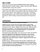
WELCOME Thank you for purchasing a HHB400 Wireless Data logging Video Inspection Camera Scope. Please read this User’s Manual carefully before using this product. The product is designed as a remote inspection device. It can be used to look into tight or inaccessible areas and wirelessly transmit real time video or still images for monitoring or recording. Typical applications may include HVAC inspection, automotive inspection, cable routing, automotive/boat/aircraft inspection, etc.
FEATURES • 12mm diameter probe, 3.28 ft. (1m) long, flexible obedient and waterproof to IP67 standards • Optional probe extensions are available to extend probe length up to 16 ft. (5m) • 3.5 in. (88.9mm) (Screen Diagonal) TFT-LCD Wireless Color Monitor can be detached from the unit for remote viewing up to 32 ft. (10m) away • Both monitor and handle use Li-ion rechargeable batteries. System comes complete with batteries and charger.
• Stay alert, watch what you are doing and use common sense. A moment of interruption can result in serious personal injury. • Do not over-reach. Keep proper footing and balance at all times. • Always wear eye protective gear. Dust mask, non-skid safety shoes, hard hat or hearing protection must be used for appropriate conditions. • Do not place the product on any unstable cart or surface. The product may fall causing serious injury to a person or serious damage to the product.
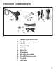
PRODUCT COMPONENTS Fig. 1 Fig. 3 10 11 Fig.
TOOL COMPONENTS Grip Handle A.Camera protection cover (Remove cover before use) B.Camera head C.Probe D.Probe connector E.Power indicator——Green lights means normal power; Red light means low battery. F.Switch / Wheel button to adjust the LED brightness G.Charging light indicator H.Charging interface Fig. 5 Monitor I. J.Locking buckle clip K.Signal connector slot L.Charging light indicator M.Charging interface N.Micro SD socket O.USB interface Fig.
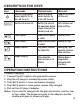
DESCRIPTION FOR KEYS Keys View mode Switch into playback mode; Hold for 3s to turn off the unit. Playback mode Switch into view mode; Hold for 3s to turn off the unit. Menu set Hold for 3s to turn off the unit. MENU Switch into menu set. Switch into current file operation, delete single all format the memory card, etc.
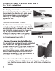
CONNECTING THE DISPLAY UNIT TO THE CAMERA HEAD AND PROBE: The display unit must be connected to the camera head and probe. To connect the probe to the display unit, make sure the keyed ends are properly aligned (See Fig. 7). Once they are aligned, tighten the nut. ACCESSORIES INSTALLATION: The three accessories include mirror tip, hook tip and magnetic tip (See Fig. 2). All are attached to the camera head the same way. Hold the camera head as shown in Fig.
• Install Micro SD card When the SD card is inserted correctly, screen; Otherwise icon will show. icon will show on the • U-disk function- attach to computer The USB interface on the screen can be connected to a computer. When inserting the memory card, it can be considered as a U-disk; When connecting the USB2.0 cable to computer and turning the power on, the LCD displays “MSDC” , now the screen can be used as U-disk.
2. How to view the screen a. Insert the Micro SD to memory card slot correctly. b. Press to enter view mode, the screen automatically find the image signal. When the same receiving and transmission frequency occurs, it is time to view image.(The default channel is CH1:2414MHZ)。 c. Press to take a photo (but if no card is inserted, the key will not function), the files will be stored in memory card itself. d.
DESCRIPTION FOR KEYS Function Menu Selection Menu Tuner Channel Photo Quality MENU Movie Quality Advanced TV Output Standard Setting EXIT Auto Capture Selection Parameter CH1; CH2; CH3; CH4; EXIT High Quality; Standard Quality; Low Quality; EXIT QVGA; D1; EXIT NTSC; PAL; EXIT Auto Capture ON; OFF; EXIT Master Capture Photo 1; Photo 3; Movie 5s; Movie 10s; EXIT File OverWrite Setting ON; OFF; EXIT EXIT Set Time/Date Photo TimeStamp Movie TimeStamp Set Time/ Resume to factory Date default EXIT YY/MM/DD O
5. This product is designed for inspection of hard-to reach areas. Typical applications include HVAC inspection, car inspection, circuitry, vessel and aircraft. OPERATION PRECAUTIONS! 1. Please read all the safety instructions carefully. 2. The probe is flexible to help you operate in hard-to-reach areas. Please don’t insert or bend by force. Please do not over bend any part of the probe. Normally, the bending radius should not be less than 2" (50mm) to prevent from permanent damage to the probe. 3.
• The red LED will light when the handle has a low battery; The “ ” will show up on the screen if the monitor has a low battery. • Do not immerse the handheld display unit in water which will result in electric shock and damages. • The camera head is water-proof, but the handheld display is not water-proof. • Do not use the product if condensation forms inside the camera head. • If the tool does not work well after turning it on. Please take the batteries out and do not use.
TROUBLE SHOOTING Problems Causes Adapter didn’t make a good connection with Will not product. charge The connector or cable is broken. Dead battery 1. Different channel The screen is set between the grip on but without and screen. image or shows 2. The probe is loose. “No Signal” 3. Stains on the camera head. LEDs on the camera head are dim at max brightness, display changes from black to white, color display turns itself off after a period. The product won’t turn on. Abnormal display or invalid keys.
FCC INFORMATION This device complies with part 15 of the FCC Rules. Operation is subject to the following two conditions: (1) this device may not cause harmful interference. (2) this device must accept any interference received, including interference that may cause undesired operation. Changes or modifications not expressly approved by the party responsible for compliance could void the user’ s authority to operate the equipment.
SPECIFICATIONS: CAMERA HANDLE/PROBE Transmission Range: Up to 32 ft. (10m), clear range without obstacle Transmission Frequency: 2414Mhz, Resolution: 320 x 240 Pixels Lighting Source: White LED Focal Length: 1.97 in (50mm) Field of View: 60° Depth of Field (DOF): 1.2" – 3.94" (30mm – 100mm) Camera Tipped Probe: 0.47" (12mm) Diameter Standard Probe Length: 3.28 ft. (1m) Standard Water proof capacity: IP67, only for obedient probe and camera head Power Source: 3.
Power Adapter: Input: AC 100 – 240 V, 50 – 60 Hz; Output: 5.5V 1.5A Image Resolution: 320 x 240 Pixels Video Resolution: QVGA/D1 Image storage media: Micro SD card(Up to 16G) Dimensions: 3.9 x 3.2 x 1 in. (100 x 82 x 26mm) Weight: 6.2 oz. (175g) Operating Temperature: 32 to 113°F (0 to 45°C) 5 to 95%RH non-condensing Storage Temperature: (-20 to 60°C) <85%RH Adapter: Input-100 to 240VAC Output: 5.5V 1.5A Charging Time: About 3.
NOTES: 17
NOTES: 18
NOTES: 19
WARRANTY / DISCLAIMER OMEGA ENGINEERING, INC. warrants this unit to be free of defects in materials and workmanship for a period of 13 months from date of purchase. OMEGA’s Warranty adds an additional one (1) month grace period to the normal one (1) year product warranty to cover handling and shipping time. This ensures that OMEGA’s customers receive maximum coverage on each product. If the unit malfunctions, it must be returned to the factory for evaluation.
Where Do I Find Everything I Need for Process Measurement and Control? OMEGA…Of Course! Shop online at omega.