
- Omega Real-Time Clock Users' Guide

25
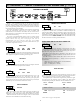
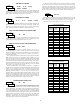
TIME DISPLAY FORMAT
ª
«
DATE DISPLAY FORMAT
AUTO CHANGE FOR DAYLIGHT SAVINGS TIME
Select the format in which the Real-Time Clock Time will be displayed. The
format selections depict the range for the RTC Time display, and DO NOT
represent the current RTC Time. When the meter is operating in the Display
Mode, the RTC Time display is shown with no annunciator.
Selecting
allows the meter to automatically adjust the RTC Time for
Daylight Savings Time. (Adjustment dates are U.S.A. standard only.) Avoid
setpoints that occur during adjustment (Sundays 1 to 3 AM).
Select the format in which the Real-Time Clock Date will be displayed. The
format selections depict the range for the RTC Date display, and DO NOT
represent the current RTC Date. When the meter is operating in the Display
Mode, the RTC Date display is indicated by the DAT annunciator.
ª
«
ª
«
ª
«
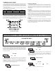
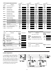
METER TYPE FOR CLOCK SYNCHRONIZATION
Time synchronization between multiple PTC901 meters can be
accomplished through a hardware interface on the Real-Time Clock option
card. This RS485 type interface allows connection of up to 32 PTC901 meters
in a two-wire multidrop network, at distances up to 4000 ft. (See Section 4.6,
Real-Time Clock Wiring).
In a Synchronization network, one PTC901 meter is programmed as the Host
(), while all other meters are programmed as Slaves (). Once every
hour (at 30 min. past the hour), the Host meter outputs a time synchronization
pulse onto the network. Upon receiving the synchronization pulse, each Slave
meter automatically adjusts the Minutes and Seconds of its RTC Time setting to
synchronize with the Host. Synchronization, using the Real-Time Clock Wiring,
adjusts the Minutes and Seconds only, and does not change the Hours, AM/PM,
Day or Date settings in the Slave meter's RTC.
Full-time synchronization (hours, minutes and seconds) is possible for
PAXCKs that are connected in an RS485 network (RS485 Serial Option cards
required). In this configuration, one meter is designated as the Serial RTC
Master by setting the meter's address as 98 or 99 (see Serial Real-time Clock
Addressing in Master Module 7). Every hour (at 30 min past the hour), the
Serial RTC Master / Host will transmit the full time (Hours, minutes, seconds)
to all meters through the RS485 serial card wiring network. The time, date, or
day will also be transmitted and updated in the Slaves when changed in the
programming of the Serial RTC Master. Only one meter should be configured
as Master and that meter should also be configured as the Host.
ª
«
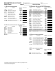
CALIBRATE REAL-TIME CLOCK
The Real-Time Clock circuit uses a crystal controlled oscillator for high
accuracy timekeeping. The oscillator is factory calibrated* and optimized for
25°C ambient temperature operation. Since the PTC901 is designed to operate
over a wide temperature range, and since the accuracy of a crystal oscillator
varies with ambient temperature, some drift in the RTC time may be observed
over an extended period. This is primarily seen in high or low temperature
installations. To compensate for the wide operating temperature range, a
calibration or “Offset” value can be entered, which effectively slows down or
speeds up the clock to maintain accurate timekeeping.
* NOTE: DO NOT ADJUST TRIM CAP ON RTC CARD!
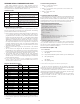
12-59p 12-59 23-59
+B/ sun-31
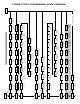
IF RTC CLOCK GAINED TIME:
USE VALUE FROM THIS TABLE
31163
30158
29153
28148
27142
26137
25132
24
21111
127
20105
23
19100
121
1895
22
1790
ENTER THIS
OFFSET
VALUE
116
SECONDS
GAINED IN
30 DAYS
1684
1579
1474
1369
1263
1158
1053
0947
08
0526
42
0421
07
0316
37
0211
06
015
ENTER THIS
OFFSET
VALUE
32
SECONDS
GAINED IN
30 DAYS
ª
«
Selecting for the parameter displays the sub-menu where the
present Offset value can be viewed or changed. The tables below show the
value to enter, given the amount of time gained or lost in a 30-day period.
Values 00 and 32 provide no Offset, and are not shown in the tables.
to
IF RTC CLOCK LOST TIME:
USE VALUE FROM THIS TABLE
63327
62316
61306
60295
59285
58274
57264
56
53221
253
52211
55
51200
243
50190
54
49179
ENTER THIS
OFFSET
VALUE
232
SECONDS
LOST IN 30
DAYS
48169
47158
46148
45137
44127
43116
42105
4195
40
3753
84
3642
39
3532
74
3421
38
3311
ENTER THIS
OFFSET
VALUE
63
SECONDS
LOST IN 30
DAYS
To calibrate the RTC, install the meter in its normal operating environment,
and set the time based on a known accurate reference (such as the WWV
broadcast or the Atomic Clock reference which is available via the internet).
After 30 days of normal operation, compare the RTC time to the reference, and
note the amount of time gained or lost. Refer to the tables on the next page for
the proper Offset value to enter, given the amount of time drift observed.