
- Omega Real-Time Clock Users' Guide

18
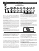
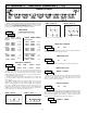
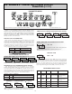
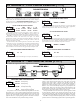
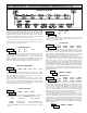
Timing Diagrams for Predefined Timer Operating Modes
NOTE: Input A is shown as a Sourcing input (active high). If a Sinking input (active low) is used, the logic levels for Input A would be inverted.
Input A
Output 1
T1
T2
T
T1
Input A
Output 1
T
T
Input A
Output 1
T
T
Input A
Output 1
T
T
Input A
Output 1
T T
Input A
Output 1
T1 T
T2
On-Delay Timing
On-Delay / Interval Timing
Repeat Cycle Timing
Interval Timing (Edge triggered)
Off-Delay Timing
Interval Timing (Level triggered)
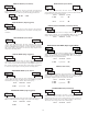
The input signal must be wired to both the Input A and
User Input 1 terminals. The Timer Input plug jumper and
the User Input plug jumper must both be set to the
same position (either both SNK or both SRC).
The input signal must be wired to both the Input A and
User Input 1 terminals. The Timer Input plug jumper and
the User Input plug jumper must be set to opposite
positions (one SNK, one SRC) and the Input signal must
be a current sinking type (i.e. pulls input to common).
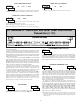
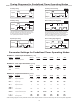
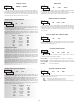
Parameter Settings for Predefined Timer Operating Modes
MODULE 1 - Timer Input Parameters ()
MODULE 2 - User Input Parameters ()
MODULE 6 - Setpoint Parameters (
)
P-UP-1
Lit-1
OrSd-1
AUtO-1
tstP-1
tOUt-1
SPOf-1
OFf-1
SP-1
ON-1
OFFOFFOFFOFFOFFOFF
Power-up State
NOrNOrNOrNOrNOrNOr
Setpoint Annunciator
NONONONONONO
Output Reset w/display Reset
NONONO0-OFFNONO
Timer/Counter Auto Reset
0-OFF0-OFF0-OFFNO0-OFFNO
Timer Stop
T*N/AT2*N/AN/AN/ATime-out Value
N/AT*N/AT2*T*N/ASetpoint Off Value
N/A
VALUE
N/A
VALUEVALUE
N/ASetpoint Off
N/AN/AT1*T1*N/AT*Setpoint On Value
t-Strtt-StrtVALUEVALUEt-StrtVALUE
Setpoint On
NOrNOrNOrNOrNOrNOr
Output Logic
t-OUtON-OFFt-OUtON-OFFON-OFFLAtCH
Setpoint Action
t-dSPt-dSPt-dSPt-dSPt-dSPt-dSP
Setpoint Assignment
SP-1SP-1SP-1SP-1SP-1SP-1
Setpoint Select
INt-EINt-LdLYINtrEPEAtOF-dLYON-dLY
PARAMETER
OUt-1
ACt-1
ASN-1
SPSEL
DISPLAY
EdrS-2 EdrS-2 EdrS-2LEVrStEdrS-2EdrS-2
Timer Input Operation
rEPEAt dLYINt INt-EINt-LOF-dLYON-dLY
PARAMETER
INP OP
DISPLAY
NO
N/A
OrSt-E
NO
N/A
NO
N/A
NO
rSt-L
NO
N/A
Reset Key
User Input 1
INt-EINt-LdLYINtrEPEAtOF-dLYON-dLY
PARAMETER
rSt
USEr-1
DISPLAY
* Refer to timing diagrams. These parameters are the actual Setpoint On/Off or Time-Out values set by the user for the specific application.
(SP1-YES)
NO