User’s Guide Shop online at www.omega.com e-mail: info@omega.
OMEGAnet ® Online Service www.omega.com Internet e-mail info@omega.com Servicing North America: USA: ISO 9001 Certified Canada: One Omega Drive, P.O. Box 4047 Stamford CT 06907-0047 TEL: (203) 359-1660 e-mail: info@omega.com 976 Bergar Laval (Quebec) H7L 5A1, Canada TEL: (514) 856-6928 e-mail: info@omega.
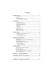
Contents INTRODUCTION..........................................................................1 OVERVIEW................................................................................................ 1 W HAT ’S INCLUDED ................................................................................ 1 FACTORY DEFAULT SETTINGS ............................................................ 1 CARD SETUP ..............................................................................2 A DDRESS SELECTION.........
RS-232..................................................................................................... 12 RS-422..................................................................................................... 12 RS-485..................................................................................................... 13 APPENDIX D - ASYNCHRONOUS COMMUNICATIONS ...............14 APPENDIX E - SILK-SCREEN ....................................................15 APPENDIX F - COMPLIANCE NOTICES .......
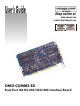
Introduction Introduction Overview The OMG-COMM2-EX provides the PC with 2 asynchronous serial ports providing a versatile interface field selectable as RS-232 for modems, printers and plotters, as well as RS-422/485 for industrial automation and control applications. What’s Included The OMG-COMM2-EX is shipped with the following items. If any of these items are missing or damaged, contact the supplier.
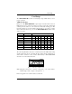
Card Setup Card Setup The OMG-COMM2-EX contains several jumper straps which must be set for proper operation. Address Selection Each port on the OMG-COMM2-EX occupies eight consecutive I/O locations. A DIP-switch is used to set the base address for these locations. Be careful when selecting the base address as some selections conflict with existing ports. The following table shows several examples that typically do not cause a conflict.
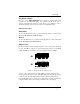
Card Setup Port Enable / Disable Each port on the OMG-COMM2-EX can be enabled or disabled with switch position 8 on the DIP-switch. The port is enabled with the switch ‘On’ or ‘Closed’ and disabled when ‘Off’ or ‘Open’. If any port is disabled, be sure to disable the interrupt request for that port by removing the IRQ jumper. Interface Selection RS-422/485 To select the RS-422/485 mode of operation install dip shunts in sockets found at E6 and E7. E6 sets Port 1 and E7 sets Port 2.
Card Setup Interrupt Modes Headers E9 and E10 select the interrupt modes for each port. Each port must be set in the correct mode to insure proper installation. E10 sets Port 1 and E9 sets Port 2 E10 ‘N’ indicates the (N)ormal, single interrupt per port mode. ‘S’ Indicates the (S)hared interrupt mode, which allows more than one port to access a single IRQ. Any two or more ports can share a common IRQ by placing the jumpers on the same IRQ setting, and setting the appropriate selections at E1.
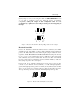
Card Setup E10 Set the jumper to ‘S’ if you are using more than one OMG-COMM2-EX in a bus or you wish to completely remove the pull-down resistor for hardware compatibility. Setting the adapter in this configuration when it is not accompanied by a pull-down resistor will prevent the ports from triggering an interrupt.
Installation Installation The OMG-COMM2-EX can be installed in any of the PC expansion slots, but to access the ‘AT’ or (E)ISA IRQs (10 - 15) it must be installed in one of the 16 bit slots. The OMG-COMM2-EX contains several jumper straps for each port which must be set for proper operation prior to installing the adapter into the comp uter. 1. 2. 3. 4. Turn off PC power. Disconnect the power cord. Remove the PC case cover. Locate an available slot and remove the blank metal slot cover.
Technical Description Technical Description The OMG-COMM2-EX adapter utilizes the 16550 UART chip. This chip features programmable baud rate, data format, interrupt control and has a 16 byte transmit and receive FIFO. Features • Full independent operation of ports allowing two ports RS-232, two ports RS-422/485 or one port of each. • Addressable as COM1: - COM4: or any other I/O address up to 3FF Hex.
Technical Description Connector Pin Assignments RS-232 (Male DB9) TD RTS DTR GND RD DCD DSR CTS RI Name Transmit Data Request To Send Data Term Ready Ground Receive Data Data Carrier Detect Data Set Ready Clear To Send Ring Indicator Pin # 3 7 4 5 2 1 6 8 9 Mode Output Output Output Input Input Input Input Input Note: These assignments meet EIA/TIA/ANSI-574 DTE for DB-9 type connectors.
Specifications Specifications Environmental Specifications Specification Temperature Range Humidity Range Operating 0º to 50º C (32º to 122º F) 10 to 90% R.H. Non-Condensing Storage -20º to 70º C (-4º to 158º F) 10 to 90% R.H. Non-Condensing Manufacturing • IPC 610-B Class-III standards are adhered to with a 0.1 visual A.Q.L. and 100% Functional Testing. • All Printed Circuit boards are built to U.L. 94V0 rating and are 100% electrically tested.
Appendix A - Troubleshooting Appendix A - Troubleshooting Serial Utility test software is supplied with the adapter and will be used in the troubleshooting procedures. By using this software and following these simple steps, most common problems can be eliminated without the need to call Technical Support. 1. Identify all I/O adapters currently installed in your system. This includes your on-board serial ports, controller cards, sound cards etc.
Appendix B - How To Get Assistance Appendix B - How To Get Assistance Please refer to Troubleshooting Guide prior to calling Technical Support. 1. Begin by reading through the Trouble Shooting Guide in Appendix A. If assistance is still needed please see below. 2. When calling for technical assistance, please have your user manual and current adapter settings. If possible, please have the adapter installed in a computer ready to run diagnostics. 3.
Appendix C - Electrical Interface Appendix C - Electrical Interface RS-232 Quite possibly the most widely used communication standard is RS-232. This implementation has been defined and revised several times and is often referred to as RS-232 or EIA/TIA-232. The IBM PC computer defined the RS-232 port on a 9 pin D sub connector and subsequently the EIA/TIA approved this implementation as the EIA/TIA-574 standard.
Appendix C - Electrical Interface RS-485 RS-485 is backwardly compatible with RS-422; however, it is optimized for partyline or multi-drop applications. The output of the RS-422/485 driver is capable of being Active (enabled) or Tri-State (disabled). This capability allows multiple ports to be connected in a multi-drop bus and selectively polled. RS-485 allows cable lengths up to 4000 feet and data rates up to 10 Megabits per second. The signal levels for RS-485 are the same as those defined by RS-422.
Appendix D - Asynchronous Communications Appendix D - Asynchronous Communications Serial data communications implies that individual bits of a character are transmitted consecutively to a receiver that assembles the bits back into a character. Data rate, error checking, handshaking, and character framing (start/stop bits) are pre-defined and must correspond at both the transmitting and receiving ends.
Appendix E - Silk-Screen Appendix E - Silk-Screen 3.9" 6.9" 4.
Appendix F - Compliance Notices Appendix F - Compliance Notices Federal Communications Commission Statement FCC - This equipment has been tested and found to comply with the limits for Class A digital device, pursuant to Part 15 of the FCC Rules. These limits are designed to provide reasonable protection against harmful interference when the equipment is operated in a commercial environment.
WARRANTY/DISCLAIMER OMEGA ENGINEERING, INC. warrants this unit to be free of defects in materials and workmanship for a period of 13 months from date of purchase. OMEGA’s WARRANTY adds an additional one (1) month grace period to the normal one (1) year product warranty to cover handling and shipping time. This ensures that OMEGA’s customers receive maximum coverage on each product. If the unit malfunctions, it must be returned to the factory for evaluation.
Where Do I Find Everything I Need for Process Measurement and Control? OMEGA…Of Course! Shop online at www.omega.