User’s Guide MADE IN Shop online at omega.com e-mail: info@omega.com For latest product manuals: omegamanual.
OMEGAnet ® Online Service omega.com Internet e-mail info@omega.com Servicing North America: U.S.A.: ISO 9001 Certified Canada: One Omega Drive, Box 4047 Stamford, CT 06907-0047 Tel: (203) 359-1660 e-mail: info@omega.com 976 Bergar Laval (Quebec) H7L 5A1, Canada Tel: (514) 856-6928 e-mail: info@omega.ca FAX: (203) 359-7700 FAX: (514) 856-6886 For immediate technical or application assistance: U.S.A.
Unpacking Instructions Remove the Packing List and verify that you have received all equipment, including the following (quantities in parentheses): Peristaltic Pump (1) Mounting Screws * (2) Operator’s Manual (1) *Long Mounting Screws (2) Optional If you have any questions about the shipment, please call the Customer Service Department. When you receive the shipment, inspect the container and equipment for signs of damage. Note any evidence of rough handling in transit.
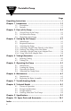
TABLE OF CONTENTS Peristaltic Pump Page Unpacking Instructions ................................................................ i Chapter 1 Introduction .......................................................... 1-1 1.1 1.2 Description ............................................................................... 1-1 Features .................................................................................... 1-1 Chapter 2 Parts of the Pump ................................................. 2-1 2.1 2.
I Index A Adapter Plate ........................................................... 3-6 Adapter Plate Specifications .................................. 3-8 C Clamp Screw Adjustment ...................................... 5-5 Creeping of Tubing ................................................. 5-5 F Flow Rates ................................................................ 1-1 M Mounting Screw Types .......................................... 3-1 P Pump Attaching ... One pump to the Motor ...............
I Index Notes II
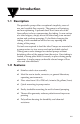
1 Introduction 1.1 Description The peristaltic pump offers exceptional simplicity, ease-ofuse, and variable flow capacity. The pump is self-priming and non-siphoning. It prevents back flow since one of the three rollers is always compressing the tubing. As one section of a tube fatigues, simply move the tube along to an unused section and continue pumping. To facilitate changing the tubing, a latch mechanism allows for easy opening and closing of the pump. No tools are required to load the tube.
1 Introduction Notes 1-2
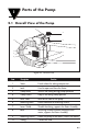
2 Parts of the Pump 2.1 Overall View of the Pump 8 4 1 3 7 6 2 10 5 Figure 2-1.
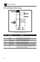
2 Parts of the Pump 2.2 Left Side of the Pump 4 7 1 5 8 2 Figure 2-2.
Parts of the Pump 2 2.3 Right Side of the Pump 4 3 8 7 5 Figure 2-3.
2 Parts of the Pump Notes 2-4
3 Setting Up the Pump(s) 3.1 Introduction To attach a single pump directly to a pump motor, follow the procedure in Section 3.3.1. To stack two pumps to a motor, follow the procedure in Section 3.3.2. To attach the pump to an adapter plate (for your own motor), follow the procedure in Section 3.3.3. To use your own adapter plate, follow the procedure in Section 3.3.4. NOTE Before you mount the pump to any pump motor, make sure that power to the motor is turned off. 3.
3 Setting Up the Pump(s) 3.3 Attaching the Pump 3.3.1 Attaching a Single Pump Directly to the Motor Refer to Figures 3-1 through 3-4 and Figure A. TOP ALIGNMENT PIN FACE OF MOTOR BOTTOM ALIGNMENT PIN ROTOR SHAFT MOUNTING HOLES MOTOR SHAFT FLAT HEAD SCREWDRIVER Figure 3-1. Pump in Closed Position Figure 3-2. Aligning the Rotor Shaft FACE OF MOTOR STANDARD MOUNTING SCREWS Figure 3-3. Aligning the Pins and Holes 3-2 Figure 3-4.
Setting Up the Pump(s) 3 1. Refer to Figure 3-1. Make sure the pump is in the closed position. 2. Refer to Figure 3-2 and Figure A. Place the blade of a flathead screwdriver in the groove of the Rotor Shaft (5). Rotate the Rotor Shaft until its back tab slips into the groove of the motor shaft. Do not try to force the pump onto the motor until you perform Step #3. 3. Refer to Figure 3-3 and Figure A.
3 Setting Up the Pump(s) 3.3.2 Stacking Two Pumps onto One Motor Refer to Figures 3-5 through 3-7 and Figure B. FACE OF MOTOR FACE OF MOTOR FIRST PUMP FIRST PUMP SECOND PUMP SECOND PUMP FLAT HEAD SCREWDRIVER Figure 3-5. Placing the Second Pump on Top of the First Pump Figure 3-6. Aligning the Rotor Shaft of the Second Pump LONG MOUNTING SCREWS Figure 3-7.
Setting Up the Pump(s) 3 1. Refer to Figures 3-1 through 3-3. Perform Steps 1, 2 and 3 in Section 3.3.1 to put the first pump on the face of the motor. 2. Refer to Figure 3-5 and Figure B. Make sure the second pump is in the closed position. 3. Refer to Figure 3-6 and Figure B. Place the blade of the flathead screwdriver in the groove of the Rotor Shaft (5) of the second pump. Rotate the Rotor Shaft of the second pump until it’s back tab slips into the groove of the Rotor Shaft of the first pump. 4.
3 Setting Up the Pump(s) 3.3.3 Attaching a Single Pump to an Adapter Plate Refer to Figures 3-8 through 3-11 and Figure C. ALIGNMENT PINS MOTOR SHAFT MOUNTING HOLES VENDOR MOTOR THREADED HOLES TO MOUNT ADAPTER PLATE TO VENDOR MOTOR (4X) ALIGNMENT PINS FOR PUMP (2X) ADAPTER PLATE CLEARANCE HOLES FOR VENDOR MOTOR ALIGNMENT PINS (2X) Figure 3-8. Mounting the Adapter Plate Figure 3-9.
Setting Up the Pump(s) 3 The adapter plate is designed to have the same alignment pins and mounting holes as the front face of the standard pump motor. It acts as an interface between a non-standard pump motor and the peristaltic pump. The non-standard pump motor must have a motor shaft groove large enough to accept the the pump rotor shaft. It must also have at least two 8-32 mounting holes aligned with those on the adapter plate (refer to Figure 3-12).
3 Setting Up the Pump(s) 3.3.4 Using Your Own Adapter Plate Figure 3-12 shows the dimensions of the front of the pump and the rear of the pump. These diagrams enable you to locate and drill out the proper size holes so you can mount the pump to a motor using your own adapter plate. Note: The rotor shaft extends out 0.563 beyond the back surface of the pump. Figure 3-12.
Setting Up the Pump(s) 3 Notes 3-9
4 Tubing Information 4.1 Selecting Tubing Select a tubing material and size that is right for your application (the fluid and flow rate that you are pumping). Table 9-2 in Chapter 9, shows the average flow rates for different size tubing. Normalized flow rates (mL per revolution) vary significantly, based on motor speed, tubing materials, viscosity, and mechanical tolerances in pump dimensions.
4 Tubing Information Notes 4-2
Operating the Pump 5 5.1 Introduction This chapter discusses the following topics: • Loading the tubing (Section 5.2) • Operating the Pump (Section 5.3) and • Adjusting the Clamp Screw (Section 5.4). Read each section thoroughly to guarantee successful pump operation.
5 Operating the Pump 5.2 Loading the Tubing NOTE Before you load the tubing in the pump, make sure that power to the motor is turned off and that the rotor has come to a complete stop. The rotor is partially exposed when the pump is in the open position. Follow this procedure (refer to Figures 5-1 through 5-4 and Figure D): Figure 5-1. Opening the Stator Figure 5-3. Closing the Stator 5-2 Figure 5-2. Loading the Tubing Figure 5-4.
Operating the Pump 5 1. Refer to Figure 5-1 and Figure D. Snap open the Stator (1) by pushing the spring-loaded area of the Latch (2). Remove any old tubing from the pump, if necessary. 2. Refer to Figure 5-2 and Figure D. Loop the Tubing (10) over the rollers. This is easy to do even for stacked pumps. NOTE Tubing can be changed on stacked pumps without detaching either of the pumps from the motor. 3. Refer to Figure 5-3. Push the stator closed until you hear the latch engage. 4.
5 Operating the Pump 5.3 Operating the Pump With the pump set up, adjust all control settings for the pump motor and start pumping. Figure 5-5 shows fluid flow directions with respect to motor directions. Extensive testing has shown that the minimum motor speed required to prime the tubing varies significantly with the size of the tubing. These variances are shown in Table 9-1 in Chapter 9.
Operating the Pump 5 MOTOR TURNING CLOCKWISE OUTLET INLET Figure 5-5b. Inlet and Outlet Flow 5.4 Adjusting the Clamp Screw Once you start the pump, you may need to adjust the Clamp Screw (4) slightly, to prevent the tube from creeping (moving) through the pump. Creeping tends to occur on tubing of larger sizes and tubing made from low friction materials (for example, Santoprene). Use the following procedure to eliminate creeping. Refer to Figure 5-6. 4 (Clamp Screw) Figure 5-6.
5 5-6 Operating the Pump 1. Turn the pump motor off. 2. Rotate the clamp screw a quarter turn clockwise, in order to increase the pressure of the clamp plate on the tube. 3. Turn the motor power back on and observe the tubing. If the tubing has not stopped creeping, go back to Step 1. Otherwise, continue pumping.
Operating the Pump 5 Notes 5-7
Maintenance 6 6.1 Introduction • No lubrication is required for the pump. All bearings are pre-sealed and rated for long life. • After many hours of use, fine particles of tubing will tend to accumulate inside the pump and on the rollers. Use a high pressure air hose (60 PSI) to blow out most of the particles from the pump. Clean all parts with a mild soap solution or a light mineral oil. • The pump may be dismantled either for cleaning or for replacing the rotor assembly in case of a malfunction.
6 Maintenance 6.2 Replacing the Rotor Assembly (Part Number FPU500-RA) In the replacement kit you will find one Rotor Assembly (13) and two Washers (12). Figure 6-1 shows the exploded view of the pump. Figure 6-1.
Maintenance 6 1. Using a phillips head screwdriver, remove the two #6 SelfTapping Screws (14) on the back of the base that hold the pump together. 2. Pull apart the three major plastic assemblies in the pump – the Lower Shield (7), Base (8), and Stator (1) Assemblies. A 3⁄16" x 13⁄4" long Alignment Pin (11) aligns the three assemblies and can be left sitting in the base. The Rotor Assembly (13) rotates within ball bearings pressed into the Base and Lower Shield.
6 Maintenance Notes 6-4
7 Troubleshooting Guide Problem No flow out of the outlet tubing Solution 1. Check to see that the Stator is snapped shut. If it is, push down on the Stator while the motor is running. This action enhances the self-priming capability of the pump. 2. Make sure the tubing is loaded properly. The tubing should be centered in the middle of the rollers. Reload if necessary. 3. Check to see that the tubing has no holes or cracks. Replace with new tubing, if necessary. 4.
7 Troubleshooting Guide Problem Fluid flows in the opposite direction of what is intended Solution 1. Check tubing connections to source and drain containers. 2. Check that the motor is rotating in the correct direction. Refer to Figure 5-5. Fluid flow direction cannot be reversed The motor only turns in one direction. Make sure you use a bi-directional motor. The tube moves when pumping Adjust the Clamp Screw. Refer to Section 5.4. The Stator will not snap shut 1.
Troubleshooting Guide Problem Motor will not turn 7 Solution 1. Make sure the tubing is loaded properly. The tubing should be centered in the middle of the rollers. Reload if necessary. 2. Check to see if the motor is turned on. 3. Check motor fuse. Motor will not turn – overcurrent condition 1. Make sure the tubing is loaded properly. The tubing should be centered in the middle of the rollers. 2. Make sure the tubing wall thickness is correct (refer to Table 9-1). 3.
7 Troubleshooting Guide Notes 7-4
8 Technical Details 8.1 Theory of Operation A peristaltic pump is a fluid pump which operates to create a moving region of compression along a flexible tube. The motion of the compressed region of the tube along its axis forces fluid ahead and creates a partial vacuum behind the region. This partial vacuum forces more fluid forward. The pump has a Rotor Assembly which rotates an attached set of rollers up against a tube backed by a fixed circular wall called the Stator.
8 Technical Details Because of the back tab and groove found in the Rotor Shaft design, pumps can be stacked one of top of another and attached to a common pump motor. Only one motor needs to be purchased to pump fluid between several different containers. The Latch Assembly of the pump allows the Stator to be easily opened and closed, allowing for quick tubing changes. Push a spring-loaded area on the Latch to open the Stator. Push the Stator shut and it snaps into place.
9 Specifications Table 9-1. Tubing Size vs Min.
9 Specifications Pump Dimensions (H x W x D): 4" x 4" x 21⁄4" (102 x 102 x 57 mm) Pump Weight: 0.9 lb (0.4 kg) Adapter Plate Dimensions (H x W x D): 3" x 21⁄2" x 1⁄8" (76 x 64 x 3.2 mm) Adapter Plate Weight: 0.2 lb (0.
Specifications 9 Table 9-2. Average Flow Rates (Cont’d) Tubing Wall Tubing Size mL per Minimum Flow Maximum Flow Thickness Inner Diameter Revolution Rate at 600 RPM Rate at 600 RPM (mL/Minute) (mL/Minute) 482 1.5 mm 3.0 mm 0.8* 8 1.5 mm 4.0 mm 1.43* 15 857 1.5 mm 5.0 mm 2.1* 21 1257 1.5 mm 6.0 mm 2.7* 27 1607 1.5 mm 7.0 mm 3.6* 37 2187 1.5 mm 8.0 mm 3.
9 Specifications Tubing operating life test were done at 600 RPM, with 20°C water, 0 PSI, back pressure until the tubing breaks. Average tubing life hours are shown. However, tubing life varies considerably depending on tubing formulation, tubing back pressure, and fluid pumped. Tubing should be inspected periodically for wear. Table 9-4. Average Tubing Life Tubing Wall Thickness (in.) Tubing Inner Diameter (mm) Material Average Tubing Life (Hours) ⁄16 1.5 Viton 10 ⁄16 1.5 1 ⁄16 1.5 1 ⁄8 3.
9 Specifications Table 9-4. Average Tubing Life (Cont'd) ⁄16 1.5 1 ⁄16 1.5 ⁄16 1.5 ⁄16 1.5 ⁄16 1.5 5 ⁄16 1.5 1 ⁄16 1.5 ⁄16 1.5 ⁄16 1.5 ⁄16 1.5 1 1 1 1 1 1 1 1 1 1 ⁄16 1.5 Vinyl 60 1 ⁄8 3.0 Vinyl 60 ⁄16 4.5 Vinyl 60 1 ⁄4 6.0 Vinyl 40 ⁄16 8.0 Vinyl 30 ⁄16 1.5 Norprene 500 1 ⁄8 3.0 Norprene 500 ⁄16 4.5 Norprene 500 1 ⁄4 6.0 Norprene 400 ⁄16 8.0 Norprene 400 3 3 5 Table 9-6.
9 Specifications Notes 9-6
10 Spare Parts and Accessories Table 10-1. Spare Parts Part Number Description FPU500-SMS Standard Length Mounting Screws FPU500-LMS Long Mounting Screws FPU500-AP Adapter Plate Assembly FPU500-RA Rotor Assembly (including washers) Table 10-2.
10 Spare Parts and Accessories Table 10-2.
Spare Parts and Accessories 10 You can use an optional Peristaltic Pump Motor (Part Number FPU5-MT) to run the pumps. Figure 10-1 shows the motor. You can attach one pump to each side of the motor or two pumps to either side. Contact Sales for more information about the pump motor. INLET SELECT LEFT PUMP INLET SELECT RIGHT PUMP RPM TIME INPUT SELECT FLOW RATE TOTAL VOLUME PRIME TEMPERATURE TUBE ID CALIBRATE START STOP Figure 10-1.
10 Spare Parts and Accessories Notes 10-4
WARRANTY/DISCLAIMER OMEGA ENGINEERING, INC. warrants this unit to be free of defects in materials and workmanship for a period of 25 months from date of purchase. OMEGA’s WARRANTY adds an additional one (1) month grace period to the normal two (2) year product warranty to cover handling and shipping time. This ensures that OMEGA’s customers receive maximum coverage on each product. If the unit malfunctions, it must be returned to the factory for evaluation.
Where Do I Find Everything I Need for Process Measurement and Control? OMEGA…Of Course! Shop online at omega.