
User manual


Hardware Setup
Card Connection
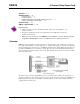
There are 16 screw terminals on the DBK25 to connect to 8 separate pairs of output contacts:
- J1 for channels 5 through 8
- J2 for channels 1 through 4
The board contains holes for use of wire ties.
Card Configuration
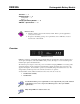
You must set DIP switch S1 to a 5-bit address to correspond to the desired card address. (S1 is located
next to the DB37 connector.) The following table lists the switch settings for 32 system card numbers.
The XI/O addresses can be used in custom programming to access specific cards.
S1 Position
OPEN = OFF
S1 Position
OPEN = OFF
System
Card #
XI/O
Address
1 2 3 4 5
System
Card #
XI/O
Address
1 2 3 4 5
0 H60 OFF OFF OFF OFF OFF 16 H70 OFF OFF OFF OFF ON
1 H61 ON OFF OFF OFF OFF 17 H71 ON OFF OFF OFF ON
2 H62 OFF ON OFF OFF OFF 18 H72 OFF ON OFF OFF ON
3 H63 ON ON OFF OFF OFF 19 H73 ON ON OFF OFF ON
4 H64 OFF OFF ON OFF OFF 20 H74 OFF OFF ON OFF ON
5 H65 ON OFF ON OFF OFF 21 H75 ON OFF ON OFF ON
6 H66 OFF ON ON OFF OFF 22 H76 OFF ON ON OFF ON
7 H67 ON ON ON OFF OFF 23 H77 ON ON ON OFF ON
8 H68 OFF OFF OFF ON OFF 24 H78 OFF OFF OFF ON ON
9 H69 ON OFF OFF ON OFF 25 H79 ON OFF OFF ON ON
10 H6A OFF ON OFF ON OFF 26 H7A OFF ON OFF ON ON
11 H6B ON ON OFF ON OFF 27 H7B ON ON OFF ON ON
12 H6C OFF OFF ON ON OFF 28 H7C OFF OFF ON ON ON
13 H6D ON OFF ON ON OFF 29 H7D ON OFF ON ON ON
14 H6E OFF ON ON ON OFF 30 H7E OFF ON ON ON ON
15 H6F ON ON ON ON OFF 31 H7F ON ON ON ON ON
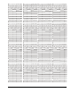
The full-page table on the following page shows all possible relay settings and their associated binary and
hex values.
DBK25, pg. 2 879795 DBK Option Cards and Modules