
User manual


User Output Configuration
The outputs of the DBK24 are designed to switch levels as high as 60 V at 1 A. The next figure shows a
typical output hookup with a protective flyback diode in parallel with the load. When driving inductive
loads without built-in flyback protection, you must provide this diode.
CAUTION
Failure to provide adequate flyback protection may result in damage to
the DBK24’s output stage.
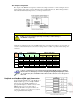
Each unit is configured via the on-board DIP switch (S1) for its unique base address. No more than one
unit in a common chain may have the same S1 setting. Below is a table of possible switch settings and
addresses.
Bank Card
No.
S1 Configuration Address Value (Hex)
C B A Port C Port B Port A
0 0 0 0 0 0x62 0x61 0x60
1 0 0 1 0x66 0x65 0x64
1 2 0 1 0 0x6A 0x69 0x68
3 0 1 1 0x6E 0x6D 0x6C
2 4 1 0 0 0x72 0x71 0x70
5 1 0 1 0x76 0x75 0x74
3 6 1 1 0 0x7A 0x79 0x78
7 1 1 1 0x7E 0x7D 0x7C
Software constants have been predefined in the DaqBook/DaqBoard driver language
interface files for all languages as follows: DdpExpnA, DdpExpnB, DdpExpnC; where
“n” is replaced by the card number in the address table; and A, B, or C is the port for
that card.
DaqBook and DaqBoard [ISA type] Connection
Connect the P2 digital I/O port of the DaqBook or
DaqBoard [ISA type] or, for a DaqBoard/2000
Series board [except DaqBoard/2003] to an
appropriate P4 adapter, to the P2 connector of the
DBK24 using an accessory cable (with -x
indicating the number of expansion units to be
connected). Select up to 8 positions for a total of
192 programmable isolated inputs.
DBK24, pg. 4 879795 DBK Option Cards and Modules