
User manual


Power Requirements
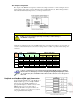
The DBK24 can be powered by an included AC adapter, a standard 12-V car battery, or an optional
rechargeable nickel-cadmium battery module (DBK30A). This power flexibility makes the DBK24 ideal
for field and remote data acquisition applications.
Power supplied to the DBK24 powers the on-board regulator. Connect the power supply (AC adapter) to
the 5-pin DIN (labeled POWER IN) located on the front panel of the DBK24 chassis. Note the two power
indicators on the rear panel of the DBK24. Check that both SYSTEM and LOCAL power LEDs are on at
all times during operation. The second 5-pin DIN connector (labeled POWER OUT) can be cascaded to
another accessory. A single power source can supply multiple DBK24 units.
CAUTION
Excessive power consumption can cause equipment damage. Calculate system power
requirements prior to daisy-chaining. Refer to Power Requirements in the DBK Basics
section for calculation tables.
Hardware Setup
Card Connection
Open the DBK24 case by loosening the two retaining screws on the chassis front panel. Slide out the
DBK24 board in order to connect wires to terminal blocks. Each input channel (or bit) is equipped with a
discrete two-pole screw terminal block for isolated HI and LOW termination. The terminals accept 12 to
22 AWG wire. Insulated wire types selected should meet or exceed 500 V isolation specifications.
DBK24, pg. 2 879795 DBK Option Cards and Modules