
User manual


Card Configuration
The LogBook, DaqBook, and DaqBoard can each support up to eight DBK23s in a daisy-chain
configuration using an accessory cable (see figure). Each unit is then configured via the on-board DIP
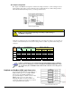
switch (S1) for its unique base address. No more than one unit in a common chain may have the same S1
setting. The table shows possible switch settings and addresses. The XI/O addresses can be used by
programmers to access specific ports on specific cards.
Software constants have been predefined in the API as follows: DdpExpnA; DdpExpnB;
DdpExpnC. Where “n” is replaced by the card number shown in the address table; and
A, B, or C is the port for that card.
Bank
Card No.
S1
Configuration XI/O Address Value (Hex)
C B A Port C Port
B
Port A
0 0 0 0 0 0x62 0x61 0x60
1 0 0 1 0x66 0x65 0x64
1 2 0 1 0 0x6A 0x69 0x68
3 0 1 1 0x6E 0x6D 0x6C
2 4 1 0 0 0x72 0x71 0x70
5 1 0 1 0x76 0x75 0x74
3 6 1 1 0 0x7A 0x79 0x78
7 1 1 1 0x7E 0x7D 0x7C
DaqBook and DaqBoard Connection
Connect the P2 digital I/O port of the DaqBook or DaqBoard [ISA type] or, for a DaqBoard/2000 Series
board [except DaqBoard/2003] to an appropriate P4 adapter, to the P2 connector of the DBK23 using an
accessory cable. Select up to 8 positions for a total of 192 programmable isolated inputs.
Note that P4 adapters are discussed in the DBK200 Series document modules.
DaqBoard/2000 Series Board Connection
Use a 37 pin accessory cable to connect the P2 digital I/O port of an appropriated DaqBoard/2000 Series
P4 adapter to DBK23’s P2. Note that you can select up to eight positions for a total of 192 programmable
isolated inputs.
P4 adapters are discussed in the DBK200 Series document modules.
P2 expansion cables must be kept short for proper operation.
Do not exceed 14” per attached DBK card.
DBK Option Cards and Modules 879795 DBK23, pg. 3