
User manual
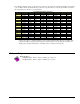


DBK21 DB37 Male P2 Connector Pinout Digital I/O
1
9
G
N
D
P
O
R
T
A
0
3
7
P
O
RT
A
1
3
6
P
O
R
T
A
2
3
5
P
O
RT
A
3
3
4
P
O
R
T
A
4
3
3
P
O
R
T
A
5
3
2
P
O
R
T
A
6
3
1
P
O
R
T
A
7
3
0
P
O
R
T
C
0
2
9
P
O
R
T
C
1
2
8
P
O
R
T
C
2
2
7
P
O
R
T
C
3
2
6
P
O
R
T
C
4
2
5
P
O
R
T
C
5
2
4
P
O
R
T
C
6
2
3
P
O
RT
C
7
2
2
G
N
D
2
1
+
5
V
2
0
8
P
O
R
T
B
2
7
P
O
R
T
B
3
6
P
O
R
T
B
4
5
P
O
R
T
B
5
4
P
O
R
T
B
6
3
P
O
R
T
B
7
2
I
R
E
N
A
BL
E
1
I
R
I
N
P
U
T
1
0
P
O
R
T
B
0
9
P
O
R
T
B
1
1
8
+
5
1
7
G
N
D
1
6
N
/
C
1
5
G
N
D
1
4
N
/
C
1
3
G
N
D
1
2
N
/
C
1
1
G
N
D
Pin Signal Name Description for P2 Pin Use
1 IR INPUT Interrupt line input (no functions to access this)
2 IR ENABLE Interrupt line enable (no functions to access this)
3 PORT B 7 Digital input/output - port B bit 7
4 PORT B 6 Digital input/output - port B bit 6
5 PORT B 5 Digital input/output - port B bit 5
6 PORT B 4 Digital input/output - port B bit 4
7 PORT B 3 Digital input/output - port B bit 3
8 PORT B 2 Digital input/output - port B bit 2
9 PORT B 1 Digital input/output - port B bit 1
10 PORT B 0 Digital input/output - port B bit 0
11 GND Digital ground
12 N/C Pin not connected/not used
13 GND Digital ground
14 N/C Pin not connected/not used
15 GND Digital ground
16 N/C Pin not connected/not used
17 GND Digital ground
18 +5 V +5 V supply (Refer to Power Requirements, DBK Basics pg. 13)
19 GND Digital ground
20 +5 V +5 V supply (Refer to Power Requirements, DBK Basics pg 13)
21 GND Digital ground
22 PORT C 7 Digital input/output - port C bit 7
23 PORT C 6 Digital input/output - port C bit 6
24 PORT C 5 Digital input/output - port C bit 5
25 PORT C 4 Digital input/output - port C bit 4
26 PORT C 3 Digital input/output - port C bit 3
27 PORT C 2 Digital input/output - port C bit 2
28 PORT C 1 Digital input/output - port C bit 1
29 PORT C 0 Digital input/output - port C bit 0
30 PORT A 7 Digital input/output - port A bit 7
31 PORT A 6 Digital input/output - port A bit 6
32 PORT A 5 Digital input/output - port A bit 5
33 PORT A 4 Digital input/output - port A bit 4
34 PORT A 3 Digital input/output - port A bit 3
35 PORT A 2 Digital input/output - port A bit 2
36 PORT A 1 Digital input/output - port A bit 1
37 PORT A 0 Digital input/output - port A bit 0
Note: There are two male DB37
connectors per DBK21 card.
Software Setup
Reference Notes:
o DaqView users - Refer to chapter 3, DBK Setup in DaqView.
o LogView users - Refer to chapter 4, DBK Setup in LogView.
Note: Refer to the full-page table on the next page for valid hex codes.
DBK Option Cards and Modules 879795 DBK20 and DBK21, pg. 3