
User manual


Hardware Setup
Card Connection
1. Connect wire leads to terminal blocks (if using a DBK20) or ribbon cable(s) terminated in 37-pin
female connectors (if using a DBK21).
2. Once all connections are in place, secure wires to the board at captive areas at the end of the card.
Nylon tie wraps (not included) work well for this purpose.
Card Configuration
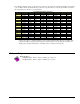
Address
Select
Hex
Value
Bank
A 0x63
0x67
0
B 0x6B
0x6F
1
C 0x73
0x77
2
D 0x7B
0x7F
3
The header shunt must be set on the proper JP1 position for
the intended address. The table shows the 4 choices
available.
Note: In multiple card systems, only 1 card at a time can
have any given setting.
Set JP1 header for the desired base address by placing the
shunt jumper in one of the positions noted in the table
(A to D). JP1 is labeled ADDRESS SELECT and is located
at the card’s lower left side.
LogBook Connection
The DBK20 or DBK21s attach to the LogBook’s P2 digital I/O connector.
P2 expansion cables must be kept short for proper operation.
Do not exceed 14” per attached DBK card.
A series of interface cables are available for connecting up to four DBK20 or DBK21
cards.
1. If using the optional DBK10 enclosure, slide the DB37 end of the board into a rear opening, and
secure with hold-in screw-washer at rear panel.
2. Connect an accessory ribbon cable (with -x indicating the number of cards to be connected) from the
digital I/O port (P2) of the LogBook to the DB37 connector at the end of the option card.
DaqBook and DaqBoard Connection
The DBK20 or DBK21s attach to the DaqBook, DaqBoard [ISA type] P2 digital I/O connector or, for a
DaqBoard/2000 Series or /2000/c Series board, to the P2 connector of an appropriate P4 adapter. P4
adapters are discussed in DBK200 Series document modules.
P2 expansion cables must be kept short for proper operation.
Do not exceed 14” per attached DBK card.
A series of interface cables are available for connecting up to four DBK20 or DBK21
cards.
1. If using the optional DBK10 enclosure, slide the DB37 end of the board into a rear opening, and
secure with hold-in screw-washer at rear panel.
2. Connect an accessory ribbon cable (with -x indicating the number of cards to be connected) from the
digital I/O port (P2) of the Daq devices or adapter to the DB37 connector at the end of the option
card.
DaqBook and DaqBoard Configuration
There are no hardware configuration setups internal to DaqBooks and DaqBoards to allow expanded TTL
I/O usage.
DBK20 and DBK21, pg. 2 879795 DBK Option Cards and Modules