
User manual


CE Compliance
Reference Notes:
Should your data acquisition system need to comply with CE standards, refer to
the CE Compliance section of the Signal Management chapter.
DaqBook/100 Series & /200 Series and DaqBoard [ISA type] Configuration
Use of the DBK18 requires setting jumpers in DaqBooks/100 Series & /200 Series devices and
DaqBoards [ISA type].
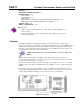
1. If not using auxiliary power, place the JP1 jumper in the Analog Option Card mode.
Note: The default position is necessary to power the interface circuitry of the DBK18 via the
internal ±15 VDC power supply. If using auxiliary power (e.g., DBK32A, DBK33), you
must remove both JP1 jumpers. Refer to Power Requirements in the DBK Basics section and
to the DBK32A and DBK33 sections, as applicable.
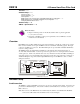
Configuration Jumpers
2. For DaqBook/100, /112, and /120 only, place the JP4 jumper in single-ended mode.
Note: Analog expansion cards convert all input signals to single-ended voltages referenced
to analog common.
DaqBook/2000 Series and DaqBoard/2000 Series Configuration
No jumper configurations are required for these /2000 series devices.
Configuring DBK18 Filter Sections
There are 4 low-pass, 3-pole active filters on the DBK18. Each filter can be enabled (EN), or bypassed
(BY) by placement of the jumper on J3 for channel 0, J4 for channel 1, J5 for channel 2, or J6 for
channel 3. The factory-default setting is bypassed (BY) for each channel.
Each filter can be configured as a Butterworth, Bessel, or Chebyshev filter with corner frequencies up to
50 kHz. Filter properties depend on the values of resistors and capacitors installed in several circuit
locations. Above 10 Hz, installing capacitors is unnecessary because capacitors in the ICs are sufficient.
In all cases, three resistors are required to complete the active filter circuits contained mostly within the
UAF42 ICs.
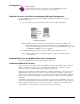
The following circuit diagram shows the active filter IC in a typical section of the DBK18. The resistors
and capacitors outside the IC have a physical location in a DIP-16 socket (dual in-line, 16 pins) with an
RCnn designator. The RC indicates the needed part is a resistor or capacitor; the 3rd character is the
channel number; and the 4th character corresponds to the socket position (A-H).
DBK Option Cards and Modules 918894 DBK18, pg. 3