
User manual


Simultaneous Sample and Hold
Some applications require every channel in a scan group to be read at the same instant, as opposed to being
read with a delay, e.g., 10 µs between channels. Simultaneous Sample and Hold (SSH) is a means of
obtaining such instantaneous data on multiple channels while avoiding time-skew problems.
A sample case in which SSH is desirable:
A performance analysis of an engine is a classic example of a case in which SSH is desirable. In our
engine analysis example data is gathered on the following parameters:
• cylinder pressure
• cylinder temperature
• piston strain
• piston stroke position
• valve position
• engine rpm
• vibration
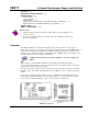
For a more exact correlation of the data, it needs to be obtained at the same instant, without time-skew. By
using SSH each input signal continuously passes through an instrumentation amplifier and into a sample-
and-hold stage. When the sample enable line goes high, each channel’s sample-and-hold stage will
“freeze” the current analog value. The values for all channels are separately “latched” within 50 ns of each
other. The signals are held [in a stable condition] while the multiplexer switches through all channels and
sends the signals [one-by-one] to the acquisition device. At the device, the ADC digitizes each reading.
The resulting data is a snapshot of conditions at a selected instant although the multiplexing and analog-to-
digital conversions are spread out over a longer interval. The simultaneous sample and hold circuit allows
you to gather up to 256 simultaneous samples via sixty-four DBK17s.
Hardware Setup
Card Connection
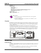
The DBK17 is equipped with BNC connectors and terminal block connectors access to each of the four
differential analog inputs. Note that the terminal block is a connection-option to the BNC connector.
Card Configuration
Factory Defaults
• 100K bias resistors – Enabled
• SSH — Enabled. No disable option.
• Gain – x1
Input Termination
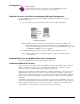
DBK17 provides two 100 KΩ bias resistors for
each analog input. For balanced 200 KΩ input
impedance, both resistors should be switched in.
An 8-position DIP switch (SW5) can selectively
engage the bias resistors. The input circuit and
switch positions are shown in the figure. The
switches must be in the closed position to engage
the termination resistors. For unbalanced high
input, only the (-) resistor should be used. If
neither resistor is used, some external bias current
path is required.
4-
4+
3-
3+
2-
2+
1-
1+
6 7 8 5 2 3
OPEN
14
+
-
AA
N
100 k
Ω
S
W5
Te r mi n a l
Block
+
_
Input Impedance/Termination
DBK17, pg. 2 879895 DBK Option Cards and Modules