
User manual


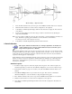


“Mode = Bridge,” Reference Route
3.
Turn off all the channels in the system except for those DBK43A channels that are to be adjusted.
4.
Click the Download button to send the current configuration to the LogBook.
5. Select Indictors \ Enable Input Reading Column from the menu bar to display the offset values for
each channel.
6.
For the associated channel, set the offset voltage to 0.0V for each transducer by adjusting the
trimpot labeled OFFSET.
Note: If you are unable to nullify the quiescent offset of the bridge, your Input Amplifier gain may be too
high. Information regarding gain redistribution can be found in the section entitled,
Determining the Gain of Each Amplification Stage.
7.
Select Indictors \ Disable Input Reading Column from the menu bar.
2-Point Calibration
This 2-point calibration method makes use of trimpot adjustments. It should not be
confused with the LogView software 2-Point Calibration (discussed in the LogView
chapter in the LogBook User’s Manual).
In the 2-Point calibration method, the user places two known loads on the gage, one at a time, then adjust
the trimpots until the expected value is reached. Typically, the first of loads is “no load.” In the case of a
weight scale, the scale would first be unloaded to adjust the offset, then a known load (near maximum
expected) would be applied to adjust the gain.
Shunt calibration (discussed immediately after this
2-Point Calibration section) is the same as the 2-Point
method, except the second load is applied in a simulated fashion by shunting 1 leg of the bridge with a
shunt resistor. Shunt calibration is preferred in cases where applying a real load (near the maximum
expected) is not practical.
Initialize the System
1. Download a single setup and continuously display data in LogView. The continuous display can
remain throughout the procedure since the calibration multiplexers do not need reset between steps.
2.
In the Param1 column (see page 19 for location), select all of the DBK43A channels that are to be
adjusted.
3.
Select Mode = Bridge from the drop down list above the grid. This selection commands the
calibration multiplexer to route the transducer voltage through the analog path.
4.
Turn off all the channels in the system, except for those DBK43A channels that are to be adjusted.
5.
Click the Download button to send the current configuration to the LogBook.
6.
Select Indictors \ Enable Input Reading Column from the menu bar to display the offset values for
each channel.
DBK16, pg. 26 879895 DBK Option Cards and Modules